SERVICE INFORMATION FOR ELECTRICAL INCIDENT
GI-45
< BASIC INSPECTION >
C
D
E
F
G
H
I
J
K
L
M
B
GI
N
O
P
INPUT-OUTPUT VOLTAGE CHART
• The voltage value is based on the body ground.
• *: If high resistance exists in the switch side circuit (caused by a single strand), terminal 1 does not detect battery voltage. Control unit
does not detect the switch is ON even if the switch does not turn ON. Therefore, the control unit does not supply power to light up the
lamp.
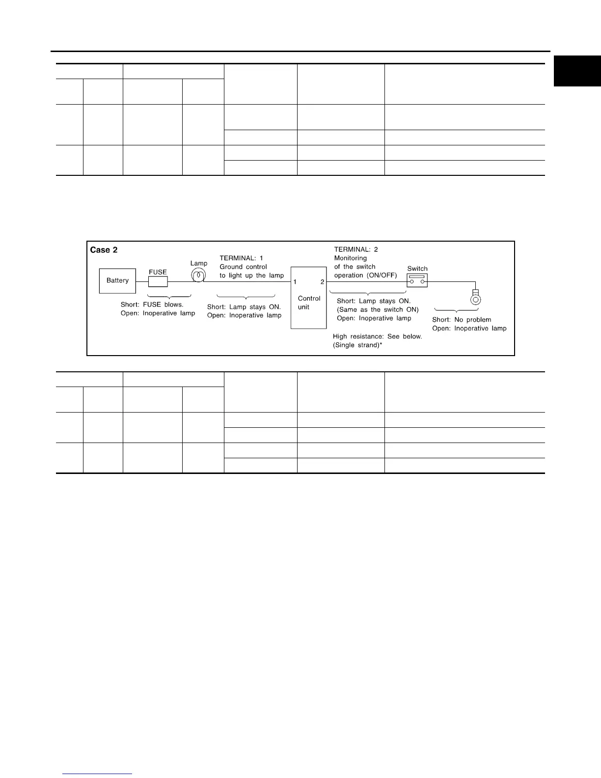
CASE 2
INPUT-OUTPUT VOLTAGE CHART
• The voltage value is based on the body ground.
• *: If high resistance exists in the switch side circuit (caused by a single strand), terminal 2 does not detect approx. 0V. Control unit
does not detect the switch is ON even if the switch does not turn ON. Therefore, the control unit does not control ground to light up the
lamp.
Terminal No. Description
Condition Value (Approx.)
In case of high resistance such as single
strand (V) *
+ − Signal name
Input/
Output
1
Body
ground
Switch Input
Switch ON Battery voltage
Lower than battery voltage Approx. 8 (Ex-
ample)
Switch OFF 0 V Approx. 0
2
Body
ground
Lamp Output
Switch ON Battery voltage Approx. 0 (Inoperative lamp)
Switch OFF 0 V Approx. 0
Terminal No. Description
Condition Value (Approx.)
In case of high resistance such as single
strand (V) *
+ − Signal name
Input/
Output
1
Body
ground
Lamp Output
Switch ON 0V Battery voltage (Inoperative lamp)
Switch OFF Battery voltage Battery voltage
2
Body
ground
Switch Input
Switch ON 0 V Higher than 0 Approx. 4 (Example)
Switch OFF 5 V Approx. 5
MGI035A
Revision: 2007 June G37 Coupe
 Loading...