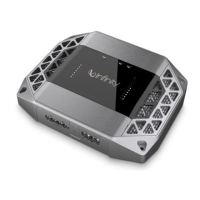
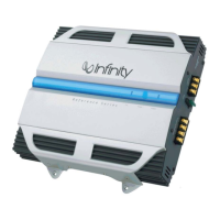
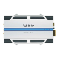
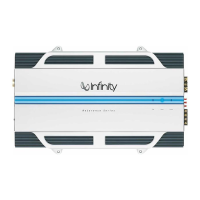
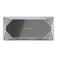
KAPPA FIVE DISASSEMBLY INSTRUCTIONS
NOTE keep track and separate any and all screws; they are dissimilar.
For examination:
1) Remove the two screws at opposite ends on the bottom of the heatsink.
2) Remove the end panel on the Input side only, four Phillips screws.
3) Slide both pieces of silver trim off the heatsink.
4) Remove the top cover; it will be attached with a cable so unplug the connector.
For most component repairs on the MAIN PCB, the entire PCB must be removed from the heatsink.
Note the 4 channel output MOSFETS (IRF6645) are an exception; skip to steps 1-5 below.
5) Remove the Output end panel, five Phillips screws.
6) Remove the terminal screws to the Power connections, and top row only of the speaker
terminals.
7) Remove the remaining four Phillips screws on the bottom of the heatsink. There are two nuts
which may spin on the machine screws; look at the top of the PCB.
8) Remove all Phillips screws holding the Aluminum transistor clamps on; remove the clamps.
Two screws holding two additional TO-220 devices should be removed.
9) Remove the Amplifier PCB; six Philips screws. The PCB will then pull straight up and off the
MAIN PCB.
10) Slide the complete PCB out of the heatsink channel.
Access to the (8) output MOSFETS Q3A, Q4A, Q5A, Q6A, Q2, Q8, Q13, Q14
1) Follow steps #1-4 above.
2) Remove the two centermost screws on the bottom of the heatsink.
3) Follow step #9 above to remove the Amplifier PCB
4) Remove the gray heatsink from the PCB by grasping and pulling it straight out – it is only held on by
friction from the white heatsink compound.
5) The (8) output MOSFETS are underneath the rectangular insulator on the PCB.
KAPPA FIVE