Do you have a question about the Infinity KAPPA FIVE and is the answer not in the manual?
Details the RMS and peak power output across different impedance loads.
Specifies the operational frequency range and signal-to-noise ratio metrics.
Lists input impedance, sensitivity, and output regulation parameters.
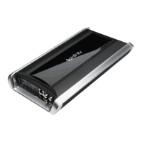
Lists and illustrates the components included in the amplifier's packaging.
Provides essential safety precautions and advice for installing the amplifier.
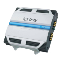
Explains how to connect power, ground, and speaker outputs correctly.
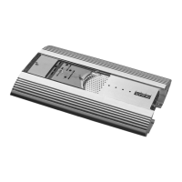
Identifies and explains the function of each control and connector on the amplifier's panel.
Offers solutions for common issues like no output, engine noise, distorted audio, and protection modes.
Shows a detailed breakdown of the amplifier's internal components and their part numbers.
Provides step-by-step guidance on how to safely take apart the amplifier for servicing.
Presents a high-level overview of the amplifier's functional blocks and signal flow.
Lists all resistors, capacitors, semiconductors, and other electronic components with part numbers.
Provides pin configuration details for various transistors, ICs, and diodes used in the amplifier.
Illustrates the physical layout of components and traces on the amplifier's printed circuit boards.
Details key features, electrical characteristics, and package information for the IC.
Shows functional blocks and typical connection diagrams for the IRS20955S driver.
Details key features, electrical characteristics, and package information for the IC.
Shows functional blocks and pin definitions for the IR2010S driver.
Lists product features, electrical specifications, and maximum operating limits.
Displays graphs illustrating typical on-resistance and gate charge characteristics.
Details the circuit diagrams for the input signal processing and preamp stages.
Illustrates the circuitry for the crossover and filter sections of the amplifier.
Provides circuit diagrams for the output amplifier stages and the power supply unit.
| Channels | 5 |
|---|---|
| RMS Power at 4 Ohms | 50W x 4 + 200W x 1 |
| RMS Power at 2 Ohms | 75W x 4 + 300W x 1 |
| Signal-to-Noise Ratio | >80dB |
| Frequency Response | 10Hz |
| THD at Rated Power | 1% |
| THD | 0.05% |
| Input Sensitivity | 200mV - 4V |
| Crossover Frequency | 32Hz – 320Hz |
| Bass Boost | 0dB – 12dB @ 45Hz |
| Crossover | Variable |