Do you have a question about the Inflight Fitness CT-MSEC and is the answer not in the manual?
| Category | Fitness Equipment |
|---|---|
| Material | Steel frame |
| Included Accessories | Water bottle holder |
| Type | Elliptical |
| Color | Silver |
Read all warning labels and consult professionals before use. Check assembly and use top weight initially.
Lists all frame parts, cushion parts, cables, pulleys, and miscellaneous components for the machine.
Details all bolts, washers, nuts, and specialized hardware required for assembly, with quantities.
Connects the Seat Frame to the Base Tube and attaches the Main Upright to this assembly.
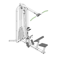
Attaches the Exercise Arm Frame, Support Assembly, and Handle Assembly to the main structure.
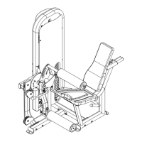
Guides the installation of the Exercise Pad, Thigh Pad Assembly, and Back Support with pads.
Installs guide rods, weight plates, top weight, and begins routing the upper cable.
Details routing and attaching the lower cable through various pulleys to the cam mechanism.
Explains how to achieve correct cable tension for machine operation, ensuring proper movement.
Covers the installation of instruction placards and weight labels onto the machine frame.
Attaches the shroud brackets and front/rear shroud panels to protect internal components.