EasyManua.ls Logo

Ingersoll-Rand 4TXK2309A1 User Manual

Ingersoll-Rand 4TXK2309A1
47 pages
To Next Page IconTo Next Page
Page #1 background imageLoading...
Page #1 background image
Installation Manual
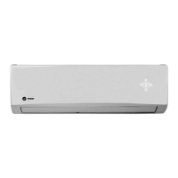
Mini-Split Inverter System
23 SEER (R-410A) High Wall Unit
9,000 - 36,000 Btu/h - 60 Hz
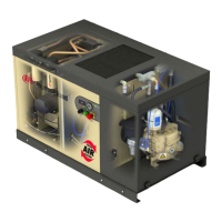
Outdoor Unit Heat Pump: AC Outdoor Unit:
4TXK2309A1 4TYK2309A1/9
4TXK2312A1 4TYK2312A1/9
4TXK2318A1 4TYK2318A1
4TXK2324A1 4TYK2324A1
4TXK2330A1 4TYK2330A1
4TXK2336A1 4TYK2336A1
Indoor Unit Heat Pump: AC Indoor Unit:
4MXW2309A1 4MYW2309A1
4MXW2312A1 4MYW2312A1
4MXW2318A1 4MYW2318A1
4MXW2324A1 4MYW2324A1
4MXW2330A1 4MYW2330A1
4MXW2336A1 4MYW2336A1
April, 2019
MS-SVN066B-EN
© 2019 Trane All rights reserved
The manufacturer follows a policy of continued improvement of their products and product data and reserve
the right to change designs and specications without prior notice. Only qualied technicians should install and
service the equipment mentioned within the present manual.
Catalogue number: MS-SVN066B-EN
Date: April 9, 2019
Replace: MS-SVN066A-EN
Question and Answer IconNeed help?

Do you have a question about the Ingersoll-Rand 4TXK2309A1 and is the answer not in the manual?

Ingersoll-Rand 4TXK2309A1 Specifications

General IconGeneral
BrandIngersoll-Rand
Model4TXK2309A1
CategoryInverter
LanguageEnglish

Summary

Warnings and Cautions

Refrigerant and Environmental Safety

Security Cautions and Warnings

Required Installation Clearances

Refrigerant Piping Safety and Procedures

Installation Location Guidelines

Indoor Unit Placement

Selecting an appropriate and safe location for the indoor unit.

Indoor Unit Mounting and Installation

Refrigerant Pipe Connection Torque

Electrical Wiring and Safety Notes

Outdoor Unit Installation and Condensate

Refrigerant Piping: Flaring and Bending

Vacuuming and Leak Detection

Electrical Connections and Wiring

Electrical Requirements and Compliance

Cable Specifications and Grounding

Post-Installation Verification and Testing

Indoor Unit Wiring Schematics (Cooling)

Indoor Unit Wiring Schematics (Heat Pump)

Indoor Unit Wiring Diagrams (Combined)

Indoor Unit Wiring Diagrams (Continued)

Outdoor Unit Wiring Diagrams (Cooling)

Outdoor Unit Wiring Diagrams (Cooling & Heat Pump)

Outdoor Unit Wiring Diagrams (Continued)

Outdoor Unit Wiring Diagrams (Details)

Outdoor Unit Wiring Diagrams (Final)

Common Error Codes and Emergency Operation

Error Detection and Troubleshooting Guide

Indoor Unit Maintenance Procedures

General Maintenance and Service

Related product manuals