Do you have a question about the Ingersoll-Rand DS35-H and is the answer not in the manual?
Instructions for connecting the dryer to the power supply safely.
Step-by-step guide for safely starting the dryer.
Periodic maintenance tasks for optimal dryer performance.
Identification and procedural advice for refrigerant leaks.
Instructions for refrigerant charging by specialists.
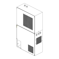
This manual describes the DS15-H-DS100-H series of refrigeration dryers, designed for professional use to provide high-quality compressed air with minimal maintenance. The dryer operates automatically and is factory-set for a dew point of 50°F (10°C), requiring no further calibration.
The refrigeration dryer removes moisture from compressed air, ensuring a dry air supply for various applications. The process involves an air-air heat exchanger, an evaporator, a refrigerant condenser, and a filter separator. Compressed air enters the dryer, passes through an aftercooler coil, and then through the filter separator. A fan motor aids in the cooling process. The unit is equipped with a compressor, a refrigerant filter, and an automatic expansion valve to manage the refrigeration circuit. Safety devices include an overload protector (SK) and, on some models, a high-pressure switch (HP). The dryer is designed to operate continuously, with its performance optimized when installed according to the manufacturer's guidelines.
Installation: The dryer should be installed indoors in a clean, dry area with an ambient temperature between 41–115°F (5-46°C), sheltered from direct weather and sunlight. It should not be installed in laundry rooms. The compressed air inlet temperature must not exceed 200°F (93°C). Adequate space around the unit is necessary for maintenance and unimpeded air discharge from the condenser. It is crucial to avoid recirculating hot condenser air back into the condenser air inlet. If the system experiences instantaneous pressure surges exceeding the dryer's rated capacity, a suitably sized receiver should be installed near the overpressure source.
A by-pass line with shut-off valves (optional) is recommended to allow maintenance or calibration without interrupting the compressed air flow. Correctly connect the dryer to the air inlet and outlet connections, using hoses if the compressed air network is prone to vibrations. If the mains are subject to high levels of pulsation, ensure the connection has pulsation dampers. Condensate drains should not be connected to other pressurized drain lines in a closed circuit, and the outflow must be unimpeded. Condensate must be disposed of responsibly according to local environmental protection norms. The ambient air around the dryer and compressor must be free of solid or gaseous contaminants, as these can generate acids or chemical products that may damage the compressor or internal components. Special care should be taken in environments with sulfur, ammonia, or chlorine, and in marine settings.
Electrical Connection: The dryer is supplied with a 3 x AWG16 power cable with a plug. An overcurrent and earth leakage circuit breaker (IDn = 0.03A) with a 0.12-inch (3 mm) gap between contacts when open must be installed upstream from the plant, adhering to local laws.
Condensate Drain: The dryer is equipped with either a float drain, a timed drain, or an electronic level sensing drain. For timed and electronic drains, refer to the separate manual provided.
Start-up and Operation: Before starting, ensure air inlet valves are closed, there is no air flow through the dryer, the mains power supply matches the dryer voltage, and the dryer is installed correctly. To start, use the switch, always activating the dryer before the air compressor. Wait approximately 5 minutes for the dryer to reach correct operating temperatures and pressures. Slowly open the air inlet valve to pressurize the dryer, then slowly open the air outlet valve. The dryer is now operating. It should remain running whenever the air compressor is operating. After stopping the dryer, wait at least 3 minutes before restarting it. To stop, use the switch, and stop the dryer 2 minutes after shutting down the air compressor or interrupting the air flow. Do not allow compressed air to enter the dryer when it is off or in an alarm state that stops the refrigeration compressor.
Safety Warnings: Keep this manual with the machine. Read it carefully before any operation. This machine is for professional use only. Improper use absolves the manufacturer from liability. Operations requiring panel removal or special tools should only be performed by trained personnel due to the risk of rotating parts or live components. Always use the electric disconnect device to isolate the machine from the mains supply before maintenance to prevent electric shocks, scalding, automatic start-up, and moving parts. Depressurize the compressed air circuit before servicing. When requesting assistance or parts, quote the model and serial number from the identification plate.
Preventive Maintenance (for optimum performance):
Substituting an Exhausted Filter Element: Wear gloves. Shut off or bypass the air supply to the dryer. Depressurize the filter using the manual or automatic drain valve (18) and leave it open. Unscrew the filter body (anticlockwise) from the head. Unscrew and remove the element (17). Clean the inside of the filter if necessary. Insert the new element (17) with a new O-ring and tighten the element. Tightly screw (clockwise) the filter body onto the head. Verify all components are properly tightened. Slowly open the air inlet shut-off valve upstream of the dryer. Allow air to flow for a few minutes, then close the drain valve (18). Open the air outlet shut-off valve downstream of the dryer.
Disassembling the Unit: The unit is designed for continuous operation. Disassembly should only be performed by a refrigerant specialist. Refrigerant liquid and lubricating oil must be recovered according to current norms in the country of installation.
Refrigerant Leaks: The unit is delivered charged as specified. Leaks may be indicated by the compressor overload protector (SK) tripping. If a leak is detected, seek technical assistance. Refrigerant charging must only be performed by a refrigerant specialist. When repairing the refrigerant circuit, collect all refrigerant in a container and dispose of it appropriately. R134a is a colorless, class A1/A1 gas with a TVL value of 1000 ppm. If a leak occurs, thoroughly air the room before commencing work.
Troubleshooting: A troubleshooting diagram is provided in the manual for various problems. For serious difficulties, contact a refrigerant specialist. Always bypass the dryer when it is out of service.
Spare Parts: A list of principal spare parts is provided. When ordering, always quote the quantity, part CPN, and machine serial number. Only use original spares supplied by the manufacturer; failure to do so voids manufacturer liability for incorrect unit operation.
| Brand | Ingersoll-Rand |
|---|---|
| Model | DS35-H |
| Category | Dryer |
| Language | English |