Programming 13
Installation and Programming manual
5-2Programming Menu
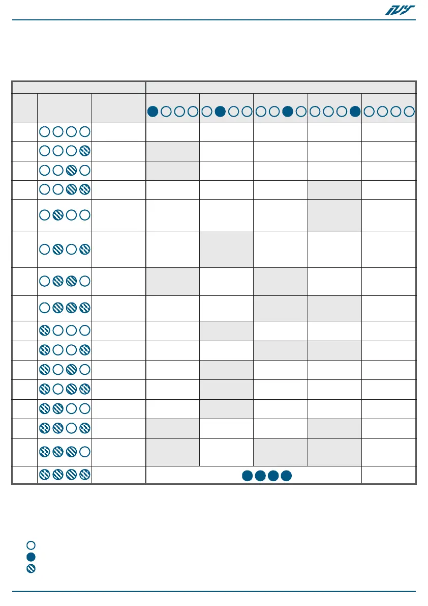
The following table shows, under the caption “Menu”, all the options on the
Programming menu and their respective LED combinations.
*: When this option is enabled, the LED STATUS becomes ON solid
• 0 - PRG LED
• 1 - Right LED on flasher circuit
• 2 - Left LED on flasher circuit
• 3 - STATUS LED
•
- LED Off
•
- LED On solid
•
- LED blinking
Table 7: Programming Menu
Menu Options
Num.
LED
combinations
Menu
options
0
Exit without
saving
////Exit
1
START Input
Negative
applied
Positive
applied
Negative
removed
Positive
removed
Deactivated
2
STOP Input
Negative
applied
Positive
applied
Negative
removed
Positive
removed
Deactivated
3
Audible
signaling
Tone 4 Tone 3 Tone 2 Tone 1 /
4
Maximum
duration of
audible
signaling
* 9 minutes 6 minutes 3 minutes /
5
Flashes
Blinking on
the LEDs
connected to
the LED Input
50 flashes/
minute
42 flashes/
minute
33 flashes/
minute
/
6
Outputs:
TAMPER and
FAULT
TAMPER
normally
closed
TAMPER
normally
open
FAULT
normally
closed
FAULT
normally
open
/
7
Activation of
the START
input
STATUS
LED
PRG
LED
Visual
signaling
Sounder Deactivated
8
Activation of
the LED input
STATUS
LED
PRG
LED
Visual
signaling
Sounder Deactivated
9
Power failure
FAULT
Output
TAMPER Output
PRG LED
Visual
signaling
Sounder Deactivated
10
Open-casing
signal
FAULT
Output
TAMPER Output
PRG LED
Visual
signaling
Sounder Deactivated
11
Foam tamper
signal
FAULT
Output
TAMPER Output
PRG LED
Visual
signaling
Sounder Deactivated
12
Blow-torch
tamper signal
FAULT
Output
TAMPER Output
PRG LED
Visual
signaling
Sounder Deactivated
13
Horn trouble
FAULT
Output
TAMPER
Output
/
STATUS LED Deactivated
14
Battery fault
FAULT
Output
TAMPER
Output
STATUS LED
(low battery)
STATUS LED
(battery
inefficient)
Deactivated
15
Reset default
Default
Exit

 Loading...