Overview 5
Installation and Programming manual
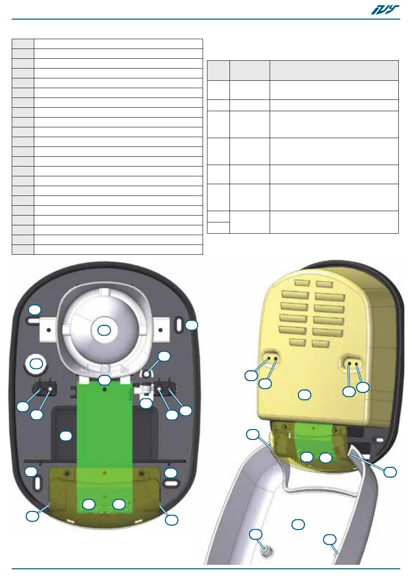
Table 4: Description of parts
A Programming button (PAGE)
B Programming button (SEL)
C Magneto-dynamic horn
D Battery housing
E Battery wires
F Terminal board
G LED flasher - left group
H LED flasher - right group
I Foam protection
J Blow-torch protection
K Dislodgement/Open tamper protection
L Wire entry
M Wall-plug locations
N Tamper-screw location
O Metal-guard screw locations
P External-casing screw locations
Q STATUS LED - Red LED
R PRG LED - Green LED
S Magneto-dynamic horn connector
T External casing in plastic
U Casing hinges
V Metal guard
Table 5: Terminal board
no.
icon/
name
Description
1+
Positive power terminal supports
13.8V
2- Negative power terminal
3START
Ancillary terminal with
programmable polarity for alarm
activation
4STOP
"Stop Alarm" terminal, with
programmable polarity for alarm
deactivation
5PRG
Input for audible/visual signaling
activation
6Output
Open-collector output for fault
signaling
I max = 100 mA
7
Output Voltage-free terminals of the relay
8
C
D
G H
I
K
L
M
M
M
M
N
O
O
P
P
U
U

 Loading...