“PLUS” (pre-set); the detector signals alarm status when smoke in the protected environment
exceeds the programmed threshold (programmed as described for the ID100 model) or when the
temperature within the protected environment exceeds the programmed threshold (programmed
as described for the ID200 model). Furthermore, in the event of a rise in temperature within the
protected environment, the sensitivity of the smoke chamber will be increased. This operating
mode, characterized by high sensitivity, allows detection of fires which produce a large amount of
flames but low smoke emission (e.g. combustion of alcohol or similar highly-inflammable pro-
ducts).
“OR”; the detector signals alarm status when smoke in the protected environment exceeds the
programmed threshold (programmed as described for the ID100 model) or when the temperature
within the protected environment exceeds the programmed threshold (programmed as described
for the ID200 model). This operating mode, characterized by medium-high sensitivity, allows
detection of fires which generate a substantial amount of smoke but low heat emission (slow bur-
ning fires) as well as fires which generate high temperatures and low smoke emission (chemical
products).
“AND”; the detector signals alarm status when the smoke and temperature in the protected envi-
ronment exceed the programmed thresholds simultaneously (programmed as described for the
ID100 model and ID200 model respectively). This operating mode, characterized by a low sen-
sitivity, lowers the false alarm rate and is useful in applications where either the smoke or heat
values in the protected environment may increase without the risk of fire.
Note
Given the limited response, consider the conditions in the protected environment carefully
before selecting this operating mode.
“SMOKE”; the detector assumes the characteristics of the ID100 model
“HEAT”; the detector assumes the characteristics of the ID200 model
LED
The bicolour LED (360° viewing) indicates the detector status.
Green blinking at 30-second intervals: detector in standby status (i.e. operating properly).
Green blinking at 5-second intervals: detector in fault status. Further details regarding the cause
of the fault (high contamination level in the smoke chamber, detector component fault, etc.) can
be obtained through the EDRV2000 driver.
Red LED On solid: detector in alarm status.
“R” terminal
The detectors have an output (terminal “R”), for the connection of an alarm repeater LED. This LED
will activate when the detector it refers to triggers an alarm.
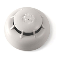
Description of the parts
A Detector
B Detector notch
C Thermal probe
D Red/green LED
E Optical chamber
F Technical specifications/serial-number sticker
G Removable serial-number stickers
H Cover removing hooks
I Optical chambre removing hooks
J Base
K Base notch 1
L Base notch 2
M “+” terminal
N “-” terminal
O “R” terminal
P Short-circuit reed
Q Screw locations
Installation
Note
For information regarding device placement, coverage and method of installation, refer to
the established standard regulations and codes relating to Automatic fire-detection
systems.
Iris series detectors are compliant with EN54-7: Smoke detectors – Point detectors using
the scattered light principle, light transmission or ionization (ID100 and ID300 models only)
and EN54-5: Heat detectors – point detectors (forID200 and ID300 models only),.
The detectors are supplied with protective covers which help to protect them against minor damage
and dust contamination which may occur during the installation phase. The covers should not be
removed until the system is ready to start up.
The detectors can be used with one of the following compatible mounting bases:
EB0010, standard base
EB0110, standard base with removable address label plate
An example of installation using standard bases is shown opposite.
EB0020, relay base
EB0120, relay base with removable address label plate
Appropriate when the detector is to be connected to an intrusion control panel or to a control panel
using 4 wires.
Note
The two removable serial-number stickers should be taken off and one should be attached
to the mounting base and the other to the installation layout.
Once the base is located properly in its placement, place the detector unit onto the base and, with
minimum force, turn it clockwise until the detector notch [B] aligns with the base notch [K] (in order to
attach the detector to the base); turn it still further until notch [B] aligns with the second base notch
[L] (in order to allow the base to engage with the detector contacts).
Using the EDRV2000 driver
The EDRV2000 driver allows you to change the operating parameters of the detectors, check the
contamination level of the smoke chambers and also obtain accurate diagnostic data. It can operate
through the USB port of a computer furnished with the relative software programme, or can function
autonomously by way of the battery housed inside.
Each detector is capable of retaining memory (smoke and/or temperature depending on the model)
of the 5 minutes prior to an alarm. Therefore, if an alarm occurs, it will be possible to obtain infor-
mation regarding the onset of the fire by simply connecting the EDRV2000 driver to the detection
line.
For further information and details regarding use of the EDRV2000 driver, refer to the respective
handbook.
Testing and maintenance
After installation and during periodic maintenance inspections, you must carry out the following ope-
rations on each detector:
Check the LED; if the LED blinks at 5 second intervals, the detector is in fault status. This may be
due to dust contamination. If after cleaning, this condition persists, remove the faulty detector and
replace it with a new one. The EDRV2000 driver will assist you in finding the cause of faults.
Optical smoke detector test; smoke detectors should be tested immediately after installation and
periodically during maintenance inspections in accordance with the established standard regu-
lations and codes in force. To test smoke detectors, use an approved test aerosol strictly in accor-
dance with the accompanying instructions.
Ensure that the smoke inlet ports to the smoke detection chamber are not blocked. Check the con-
tamination level of the smoke detection chamber via the EDRV2000. If the contamination level is
high, detach the detector from its mounting base and open the chamber then, using a small, soft-bri-
stle brush or hand-held vacuum cleaner remove all dust particles from inside and around the smoke
detection chamber.
Free the protection mesh from all contaminants.
Heat detector test; using a suitable device (e.g. hairdryer), create heat in the vicinity of the detector,
then work through the steps described in the device instruction sheet. During each periodic main-
tenance inspection, ensure that the heat element is intact and that is not obstructed by dust or paint.
If it is, using a small, soft-bristle brush or hand-held vacuum cleaner remove all contaminants.
Technical specifications
Model
ID100 ID200 ID300
Power supply from 10 to 30 V
Current draw in standby 90µA 70µA 90µA
Current draw in alarm Max 40mA
Current draw by the “R” output
(internally limited)
Max 14mA
Dimensions (DxH, standard base
included)
110 x 46 mm 110 x 54 mm
Weight
160g, standard base included
91g, without base
Environmental conditions
Temperature from -5 to +40 °C
Relative humidity ≤ 95 % without condensation
CE mark
0051
INIM Electronics s.r.l.
Via Dei Lavoratori 10 - Fraz. Centobuchi
63076 Monteprandone (AP) - Italy
10
0051-CPR-1875
EN 54-7:2000 + A1:2002 + A2:2006
ID100
Conventional optical smoke detector for fire detection
and fire alarm systems installed in buildings
0051
INIM Electronics s.r.l.
Via Dei Lavoratori 10 - Fraz. Centobuchi
63076 Monteprandone (AP) - Italy
10
0051-CPR-1874
EN 54-5:2000 + A1:2002
ID200
Conventional class P heat detector for fire detection
and fire alarm systems installed in buildings
Essential characteristics Performance
Nominal activation con-
dition/sensitivity, response delay
(respon
se time) and performance
under fire conditions
PASS
Operational reliability PASS
Tolerance to supply volt
age PASS
Durability of
operational
reliability:
Temperature resi-
stance
PASS
Vibration resistance PASS
Humid
ity resistance PASS
Corrosion resistance PASS
Electrical stability PASS
Detector class (EN54-5): A1R or B
0051
INIM Electronics s.r.l.
Via Dei Lavoratori 10 - Fraz. Centobuchi
63076 Monteprandone (AP) - Italy
10
0051-CPR-1873
EN 54-5:2000 + A1:2002
EN 54-7:2000 + A1:2002 + A2:2006
ID300
Conventional multicriteria optical smoke and class P
heat detector for fire detection and fire alarm
systems
installed in buildings
Essential characteristics Performance
Nominal activation con-
dition/sensi
tivity, response delay
(response time) and performance
under fire conditions
PASS
Operational reliabili
ty PASS
Tolerance to supply voltage PASS
Durability of
operational
reliability:
Temperature resi-
stance
PAS
S
Vibration resistance PASS
Humidity resistance PASS
Corrosion resistance PASS
Electrical stability PASS
Dete
ctor class (EN54-5): A1R or B
Documents for the users
Declarations of Performance, Declarations of Conformity
and Certificates concerning to Inim Electronics S.r.l. pro-
ducts may be downloaded free of charge from the web
address www.inim.biz, getting access to Extended Access
and then selecting "Certifications" or requested to the e-
mail address info@inim.biz or requested by ordinary mail
to the address shown in this manual.
Manuals may be downloaded free of charge from the web
address www.inim.biz, getting access to Extended Access
and then selecting "Manuals".
Warnings and limitations
Iris series detectors must be used exclusively with
fully compliant, compatible control panels. Detectors
may not provide timely warning of fire if coverage is
limited by large obstructions (pillars, large machinery,
etc.). When installing or working on a fire detection
system, always refer to and comply with the esta-
blished standard regulations and codes. Appropriate
fire-risk assessment should be undertaken to deter-
mine the type of detectors required and their pla-
cements.
Manufacturer's details
Manufacturer: Inim Electronics S.r.l.
Production plant: Centobuchi, via Dei Lavoratori 10
63076 Monteprandone (AP), Italy
Tel: +39 0735 705007
Fax: +39 0735 734912
e-mail: info@inim.biz
Web: www.inim.biz
The persons authorized by the manufacturer to repair or
replace the parts of this system, hold authorization to
work on Inim Electronics brand devices only.
About this manual
Manual code: DCMIIN1PID
Revision: 260
Copyright: the information contained in this document is
the sole property of Inim Electronics S.r.l. No part may be
copied without written authorization from Inim Electronics
S.r.l.. All rights reserved.
WEEE
lnformative notice regarding the disposal of electrical and electronic equipment (applicable in countries
with differentiated waste collection systems)
The crossed-out bin symbol on the equipment or on its packaging indicates that the product must be disposed of
correctly at the end of its working life and should never be disposed of together with general household waste. The
user, therefore, must take the equipment that has reached the end of its working life to the appropriate civic ame-
nities site designated to the differentiated collection of electrical and electronic waste. As an alternative to the autonomous-
management of electrical and electronic waste, you can hand over the equipment you wish to dispose of to a dealer when pur-
chasing new equipment of the same type. You are also entitled to convey for disposal small electronic-waste products with
dimensions of less than 25cm to the premises of electronic retail outlets with sales areas of at least 400m2, free of charge and
without any obligation to buy. Appropriate differentiated waste collection for the subsequent recycling of the discarded equi-
pment, its treatment and its environmentally compatible disposal helps to avoid possible negative effects on the environment
and on health and favours the re-use and/or recycling of the materials it is made of.
ES
Descripción general
Los detectores de la serie Iris son capaces de detectar la presencia de algunos productos de com-
bustión y por lo tanto la generación de puntos de incendio.
Los parámetros de funcionamiento de los detectores pueden ser modificados y adecuados a las
condiciones ambientales a través del dispositivo EDRV2000 entregado por Inim Electronics. A tra-
Manuale d'istruzioni / Instruction manual / Manual de instrucciones / Notice d’instructions Inim Electronics S.r.l. © 2021 DCMIIN1PID-260-20210419
 Loading...