Do you have a question about the Inkbird ITC-308 and is the answer not in the manual?
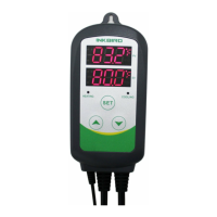
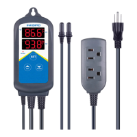
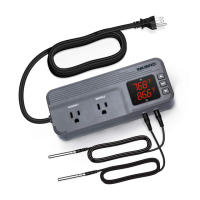
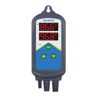
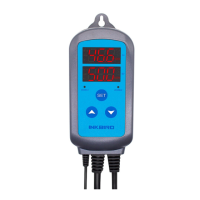
Details the plug-n-play design, dual relay output, unit support, load capacity, dual display, calibration, and alarm features.
Short press of specific keys displays heating or cooling differential values.
Procedure to enter parameter setup mode, navigate menus, and set values using SET and directional keys.
Visual representation of the sequence for setting temperature control parameters like TS, HD, CD, AH, AL, PT, CA, CF.
Sets the desired target temperature for heating or cooling operations.
Defines the temperature difference that triggers heating to start or stop.
Defines the temperature difference that triggers cooling to start or stop.
Sets the upper temperature threshold that triggers a high-temperature alarm.
Sets the lower temperature threshold that triggers a low-temperature alarm.
Sets a delay before refrigeration starts to protect the compressor.
Allows adjustment of the measured temperature to match the actual temperature.
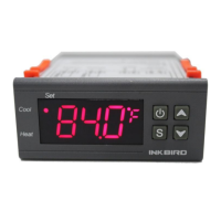
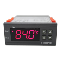
Selects the display unit for temperature: Fahrenheit or Centigrade.
Indicates a problem with the temperature sensor, showing 'ER' and sounding an alarm.
Triggers when measured temperature exceeds the safe operating range, displaying 'HL'.
Provides contact information (email, website) for installation or usage support.
Covers the one-year limited warranty against defects in workmanship or materials.
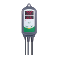
| Model | ITC-308 |
|---|---|
| Type | Temperature Controller |
| Input Power | 100-240V AC, 50/60Hz |
| Alarm | High and Low Temperature Alarm |
| Temperature Control Range | -50°C to 99°C |
| Temperature Resolution | 0.1°C |
| Temperature Accuracy | ±1°C |
| Sensor Type | NTC Sensor |
| Sensor Length | 2m |
| Control Mode | Heating, Cooling |
| Input Power Cable Length | 1.5m |
| Output Power Cable Length | 1.5 meters (4.92 feet) |
| Dimensions | 140x68x33mm / 5.5x2.7x1.3in |