DS 13.01
September 2013
Overview
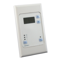
The ICS series Control Stations form part of the Maxim & Genesis
Direct Digital Controller range and provide a simple unitary
Human Machine Interface (HMI). The HMI oers on/o, setpoint
and fan speed control. The HMI is powered by 24VAC and
connects directly to the Globals Comms network.
Each ICS can communicate with a designated controller on
the network. The ICS units are configured via the Keypad, are
compatible with most existing Innotech digital products and are
capable of operating at both fast or slow comms.
The interface to the controller is via global transmit and receive
blocks, the configuration simply uses the ICS address to form
part of the unique point name.
Features
• One numerical value input
• One numerical value output
• One momentary push button digital input
• One LED indication digital output
• One fan speed input (ICS02 only)
• Housed in a switchplate that mounts in standard electrical
wall plates
• Isolated RS485 interconnection between Innotech Controllers
• Adjustable user input range
• Adjustable decimal place
• Configurable power on settings
Applications
The Innotech Control Station extends the capabilities of
Innotech controllers by providing a numerical value output,
numerical value input, push button digital input and a single LED
display output for distributed control via RS-485.
The Innotech Control Station provides a visual display of
a control value and a means to set a parameter. It is not
intended for use on a large controller network as this aects the
operation.
Installation
• Strictly follow the guidelines when installing the Comms wiring as
outlined in the Genesis System Comms Wiring Recommendations.
• Mount the Innotech Control Station in a dry and clean location free of
excess vibration.
Wiring
• DO NOT connect 240VAC to any terminals.
• The cable used for RS485 Comms must be shielded single twisted
pair, 120 ohms character impedance, 36 to 45pF per metre
capacitance between conductors.
• The Comms cable must be organised as a bus topology. That is,
starting at one end, devices are connected to it until the other end
of the cable is reached. No “stubs” are allowed. To connect a device
to the cable, a cut is made in the cable at the point where the device
is to be situated along it. Then, the two new ends of the cable are
wired into the device. The shields from the two new ends are then
terminated into the terminals marked SHLD1.
• Refer to the Genesis Network Installation Instructions and DS99.04
Cabling Manual for more information.
Approvals
The Innotech Control Station conforms to the requirements for RCM
labelling.
ICS0x
Innotech Control Station
MODEL:
ICS01: ON/OFF, Set Point
ICS02: ON/OFF, Set Point and 3 Speed Fan
Model Number Designations
Innotech Control Station - ICS0x
Model
On/O
Temp.
Display
Setpoint
Adjust
Run Status Fan Speed
ICS01
ICS02