EasyManua.ls Logo

Innotech MAXIM Miniport MP01 - User Manual

Innotech MAXIM Miniport MP01
4 pages
Print Icon
To Next Page IconTo Next Page
Loading...
© MASS ELECTRONICS Pty Ltd 2011
DS 13.03
September 2013
Overview
The MAXIM Miniport is a network device that allows a user to
externally access the Human Machine Interface (HMI) of a MAXIM
Series Controller installed on the network. The MAXIM Miniport can
be used to locate and log on to any controller on the network using
the Net Comms connection.
The MAXIM Miniport is designed for surface mounting and allows
easy access to networked controllers that are located in remote or
inaccessible areas.
Features
Access up to 40 networked MAXIM Controllers at one time
Search up to 40 controllers at one time, within a device address
range of 1-99
Access to up to 62 Sub Network devices per Sub System Gateway
on Primary Network
4 line, 80 character backlit Liquid Crystal Display (LCD)
1 x RS485 serial communications port for Net Comms
1 x RS485 serial communications port for Global Comms
Supports MAXIM Controllers that incorporate Net Comms
Network Display Mode
Network Searching Facilities
Can detect and identify GENESIS Controllers on the Network
User programmable baud rates
User programmable sleep timeout
Select button allows user to connect and disconnect from an
individual MAXIM Controller
Convenient reconnect function
Flash ROM for in-system firmware upgrades
Operates on 24 VAC or 24V DC
9600, 57600, and 115200 baud comms rate
Applications
The MAXIM Miniport can be used in a variety of situations. Its main
advantage is allowing easy access to a number of controllers from
a single point. This enables the user to access a controller without
requiring physical access to the chosen controller.
A single point of access to a MAXIM Controller network
Mounted on panel doors to give easy access to a group of MAXIM
Controllers within the control panel
Hand held Service Tool
Wall mounted device
Used as a monitoring device
Approvals
The Innotech MAXIM Miniport conforms to:
EN61326:2013 for CE Marking and RCM Labelling
Title 47 CFR, Part 15 Class A for FCC Marking
UL & C-UL listed to UL916, File Number E242628
MAXIM Miniport RS485
Human Machine Interface Version
Specifications
Power Supply
24 V AC + 10% @ 50/60Hz
24 V DC + 20%
Power Consumption: 1.5W Max
The operating voltage must meet the requirements of Safety Extra
Low Voltage (SELV) to EN60730. The transformer used must be a
Class 2 safety transformer that has the energy and voltage limiting
characteristics as described in the National Electrical Code, ANSI/
NFPA70. It must also be sized and fused in compliance with local
safety regulations.
Temperature Ratings
Storage: 0 to 50°C non-condensing
Operating: 0 to 40°C non-condensing
Terminal Identification
Power Supply
1 – 24 V Supply
2 – 0 V Supply
3 – EARTH
Terminal 3 Note: This connection is to protect the communication
circuitry, and must be connected to a good clean EARTH. It should
NOT be connected to terminal 2.
Comms Connection
SHLD1 – Shield from incoming AND to outgoing comms
+ – RS485 (+) signal
- – RS485 (-) signal
Enclosure and Mounting
The MAXIM Miniport MP01 is housed in a HPM
TM
or Clipsal
TM
style
switch plate enclosure, and is moulded from flame retardant
plastics recognised by UL as UL 94-V0.
Colour : White
Dimensions (max): (W) 117mm x (H) 72mm x (D) 28mm
Cutout: (W) 75mm x (H) 53mm (At least 16mm depth
required)
Mounting Screws: 84mm or 100mm centres
Models:
MP01 – Human Machine Interface for MAXIM Controllers
Question and Answer IconNeed help?

Do you have a question about the Innotech MAXIM Miniport MP01 and is the answer not in the manual?

Summary

Overview

Features

Specifications

Power Supply Specifications

Details the voltage and frequency requirements for the device.

Temperature Ratings

Specifies the acceptable storage and operating temperature ranges.

Applications

Approvals

Terminal and Connection Identification

Power Supply Terminals

Identifies the pinout for power input: 24V Supply, 0V Supply, and EARTH.

Comms Connection Terminals

Details the SHLD, +, and - pins for RS485 communication.

Enclosure and Mounting

Wiring

Interface

Modes of Operation

Sleep Mode

Device disconnects from network during user inactivity.

Master Mode

Device remains connected, polling the Default MAXIM controller.

Slave Mode

Device fetches and displays data from the Master MiniPort.

Communicate State

MiniPort Configuration

Configure MiniPort Menu Options

Options include Search, Setup, Devices, and Reconnect.

Setup Parameters

Configurable settings: Viewing Mode, Default Device, Sleep Delay, Comms Speed, Search Addresses.

States Summary

Sleep State

Device enters sleep after inactivity, monitors for activity.

Status LEDs

Default Mode Operation

Sleep Mode Operation

MiniPort does not allow connection during any network activity.

Master Mode Operation

MiniPort automatically logs on to the Default Device.

Slave Mode Operation

MiniPort displays the same data as the Master MiniPort.

Menu and Device Navigation

Menu Page Options

Provides access to Search, Setup, Devices, and Reconnect functions.

Devices Page Navigation

Enables selection and logging on to devices found on the network.

Logged onto a Device

MiniPort provides access to the HMI of the connected Default Device.

FCC Class A Notice

Connection Diagrams

Standard Connection

Illustrates the wiring for a standard Miniport to MAXIM connection.

End Comms Connection

Shows wiring for Miniport and MAXIM devices in an end-to-end configuration.

Mid Comms Connection

Depicts wiring for Miniport and MAXIM devices in a mid-network configuration.

Overview

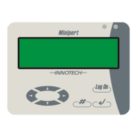
The MAXIM Miniport RS485 Human Machine Interface Version (Model MP01) is a network device designed to provide external access to the Human Machine Interface (HMI) of MAXIM Series Controllers installed on a network. It allows users to locate and log on to any controller on the network via a Net Comms connection. This device is suitable for surface mounting, offering easy access to networked controllers in remote or inaccessible locations.

Function Description:

The Miniport acts as an interface to MAXIM Controllers, allowing users to monitor and control them remotely. It supports access to up to 40 networked MAXIM Controllers simultaneously and can search for up to 40 controllers within a device address range of 1-99. It also supports up to 62 Sub Network devices per Sub System Gateway on the Primary Network.

The device features a 4-line, 80-character backlit Liquid Crystal Display (LCD) for user interaction. It includes one RS485 serial communications port for Net Comms and another for Global Comms, supporting MAXIM Controllers that incorporate Net Comms. It offers network display mode and network searching facilities, capable of detecting and identifying GENESIS Controllers on the network.

The Miniport operates in various modes:

  • Sleep Mode: The Miniport disconnects from the Innotech network during periods of user inactivity, allowing other HMIs or software to connect. It will re-enter sleep mode based on a programmable sleep delay parameter.
  • Master Mode: The Miniport remains connected to the Default MAXIM controller on the network during user inactivity, polling it every 10 seconds. It displays current data from the Default MAXIM controller and allows other HMIs or software to connect. If network activity ceases, it re-enters Master Mode.
  • Slave Mode: In this mode, the Miniport fetches and displays information from a Miniport operating in Master Mode. It will enter sleep mode and disconnect from the network if there is network activity, re-entering Slave Mode when activity ceases.
  • Communicate State: The Miniport enters this state when a user presses the Log On button and connects to a controller on the network. The Log On button can also be used to log off and disconnect.

The Miniport setup menu offers four options:

  • Search: Allows the Miniport to search for all connected devices on the network and log on to any found device, based on Start and Stop search parameters.
  • Setup: Configures Miniport parameters such as Viewing Mode, Default Device, Sleep Delay, Comms Speed, Search Start Addr, and Search Stop Addr.
  • Devices: Displays all devices found by the Miniport on the network.
  • Reconnect: Logs the user on to the device to which the Miniport was last connected.

Important Technical Specifications:

  • Power Supply:
    • 24 VAC ± 10% @ 50/60Hz
    • 24 VDC + 20%
    • Power Consumption: 1.5W Max
    • The operating voltage must meet Safety Extra Low Voltage (SELV) to EN60730. A Class 2 safety transformer with energy and voltage limiting characteristics (as described in ANSI/NFPA70) must be used, sized, and fused in compliance with local safety regulations.
  • Temperature Ratings:
    • Storage: 0 to 50°C non-condensing
    • Operating: 0 to 40°C non-condensing
  • Comms Connection:
    • Shielded single twisted pair cable (120 ohms characteristic impedance, 36 to 45pF per metre capacitance) is required for RS485 Comms.
    • The Comms cable must be connected in a bus topology.
    • Terminal 3 (EARTH +) must be connected to a good clean EARTH for communication circuitry protection, not to terminal 2.
  • Enclosure and Mounting:
    • Housed in a HPM™ or Clipsal™ style switch plate enclosure.
    • Moulded from flame retardant plastics (UL 94-V0).
    • Colour: White
    • Dimensions (max): (W) 117mm x (H) 72mm x (D) 28mm
    • Cutout (required): (W) 75mm x (H) 53mm (At least 16mm depth)
    • Mounting Screws: 84mm or 100mm centres
  • Baud Rates: User programmable, including 9600, 57600, and 115200 baud comms rates.

Usage Features:

  • User Programmable Settings: Includes baud rates, sleep timeout, and search parameters (Start/Stop Address).
  • Select Button: Allows users to connect and disconnect from individual MAXIM Controllers.
  • Convenient Reconnect Function: For quick connection to the last-accessed device.
  • Firmware Upgrades: Supports Flash ROM for in-system firmware upgrades.
  • Power Options: Operates on either 24 VAC or 24 VDC.
  • Applications: Can be used as a single point of access to a MAXIM Controller network, mounted on panel doors for easy access, as a hand-held service tool, a wall-mounted device, or a monitoring device.
  • Status LEDs: Red LED indicates data transmit, Green LED indicates data receive.
  • FCC Class A Notice: Complies with Part 15 of the FCC Rules, designed to provide reasonable protection against harmful interference in a commercial environment.

Maintenance Features:

  • Firmware Upgrades: Flash ROM allows for in-system firmware updates, ensuring the device can be kept current with new features or bug fixes.
  • Robust Construction: Housed in a flame-retardant plastic enclosure (UL 94-V0), contributing to durability and safety.
  • Standardized Wiring: Uses RS485 shielded twisted pair cable and bus topology, simplifying installation and troubleshooting.
  • Earth Connection: Requires a good clean EARTH connection for communication circuitry protection, which is crucial for reliable operation and fault prevention.

Innotech MAXIM Miniport MP01 Specifications

General IconGeneral
BrandInnotech
ModelMAXIM Miniport MP01
CategoryRecording Equipment
LanguageEnglish