18
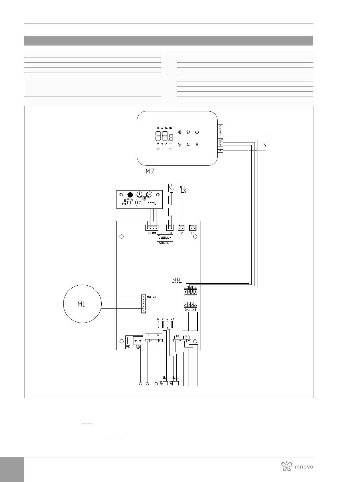
4.3 Single connection diagram
M1 Fan motor DC Inverter
PE Earth connection
L-N Power supply connection 230 V / 50 Hz / 1 A
Y1 Water electrovalve
Y2 Water electrovalve 4 pipes
CH/C1 Cooling request contact (for exemple chiller or reversible heat
pump). Activated in parallel with the solenoid valve output (Y1)
with 1 minute delay when the fancoil is in cooling mode and is
on call (potential-free contact max. 1 A).
BO/C2 Heating request contact (for example boiler or heat pump).
Activated in parallel with the output of the solenoid valve (Y1)
with 1 minute delay when the fancoil is in heating mode and is
on call (potential-free contact max. 1 A).
CP Presence contact (normally open)
-BA+ Serial connection for wall-mounted remote control (respect
polarisation AB)
IN1 Potential-free input 1(not active)
H2/T2 2-pipe water temperature probe
H4/T3 4-pipe water temperature probe
LU Electronic board for pairing control and device
PU Electronic board on the unit
H4 H2
PU
LU
For models with hydraulic connections on the right
hand side, please refer to "Models with right-hand hy-
draulic connections" p.15 to make the connections.
p. 15 section to make
the connections.
 Loading...