EasyManua.ls Logo

Innovive Innorack IVC Mouse User Manual

Innovive Innorack IVC Mouse
2 pages
To Next Page IconTo Next Page
Page #1 background imageLoading...
Page #1 background image
RACK SETUP
Innorack
®
IVC Mouse
Quick Start Guide
Supply blower(s)
Exhaust blower(s)
Controller mount
with screws
Wall mount
bracket(s)
Blower port plugs
Controller with cable
Power supply with cables Power cable
RACK COMPONENTS
Single-sided rack only
Single-sided rack (1-sm, 1-lrg)
Double-sided rack (3-sm, 2-lrg)
Before proceeding please check the package to see if
the items below have been included in the shipment.
F3
F1
F4
F5
F6
F7
F2
Controller Port
Rack to Blower Cable Port
Power Supply
Por t
Single-sided rack (1 power cable attached)
Double-sided rack (2 power cables attached)
1. INSTALLING THE POWER SUPPLY
Verify the power switch is set to the off
position ( O ).
Double-sided racks mount the power supply
on “Supply A” or “Exhaust B”. Single-sided
racks mount the power supply on the Supply
Blower end.
Secure power supply box to the top of
the rack by placing the L-shaped bosses
extending from the power supply box into the
mating feature of the plastic blower supports
(see F1).
2. MOUNTING THE CONTROLLER
NOTE - Mounting instructions are for
single-sided racks. Optional for double-
sided racks.
Attach controller mount bracket to the top
of blower support section using the screws
provided and a #2 Phillips Head screwdriver
(see F2).
Mount controller to the Controller Bracket
(see F3).
3. INSTALLING THE BLOWERS
Match the label on the front of the blower with
the corresponding label on the side of the rack.
Tilt blower back and slide the two grooves in
the back of the blower onto the two hooks at
the back of the blower support (see F4).
Check to make sure blower feet sit properly in
feet cavities. Pull the front of the blower down
until both latches on the blower engage with
the blower support. Press down on the front of
the blower to ensure that it is locked in place
Connect the Rack to Blower Cable Port
(see F5).
4. CONNECTING THE CONTROLLER
CABLE AND POWER SUPPLY CABLES
Attach the controller cable at the Controller
Port and then connect the power supply
cables at Power Supply Port as shown in F5 &
F6. Single-sided systems will only attach one
power supply cable into the Power Supply Port.
Attach the provided power cable to the power
supply box (see F7) and then plug the power
cord into a wall outlet or a power strip
(100-240 VAC).
Finally, ensure all the blowers and the
controller are plugged into the rack prior to
turning the system on and insert the Blower
Port Plugs into any unused ports.
5. TURNING THE SYSTEM ON
Press the switch on the power box located
on the top of the rack to the on position ( | ).
*Remove the wash caps before continuing with the setup process.
Question and Answer IconNeed help?

Do you have a question about the Innovive Innorack IVC Mouse and is the answer not in the manual?

Innovive Innorack IVC Mouse Specifications

General IconGeneral
BrandInnovive
ModelInnorack IVC Mouse
CategoryRacks & Stands
LanguageEnglish

Summary

Rack Setup

Installing the Power Supply

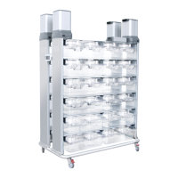
Verify the power switch is set to off. Secure power supply box to the top of the rack by placing L-shaped bosses into plastic blower supports.

Mounting the Controller

Attach controller mount bracket to the top of blower support section using provided screws and a #2 Phillips Head screwdriver.

Installing the Blowers

Match blower label to rack label, tilt blower back, slide grooves onto hooks, ensure feet sit properly, engage latches.

Connecting the Controller Cable and Power Supply Cables

Attach controller cable to Controller Port, connect power supply cables at Power Supply Port, connect power cable to supply box.

Turning the System On

Press the switch on the power box located on the top of the rack to the on position (1).

Blower Calibration

Getting to the Blower Calibration Screen

Press and hold bottom buttons 5 and 6 on the digital controller until the menu screen appears. Scroll UP or DOWN to reach Blower Calibration screen.

Disconnect HVAC Before Calibrating

Ensure the rack is disconnected from the HVAC system. Press CALIBRATE to begin, then CONFIRM to ensure disconnection.

Calibrating the Blower

After HVAC disconnection is confirmed, calibration of each blower will begin sequentially. Airflow set points are saved.

Blower Calibration is Complete

Upon successful recalibration, airflow set points are restored. The screen will display Success. Press DONE to exit.