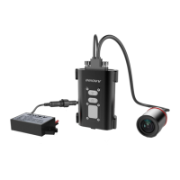
INNOVV C5
WiFi Full HD Remote Lens
Motorcycle Camera System
Installation Guide
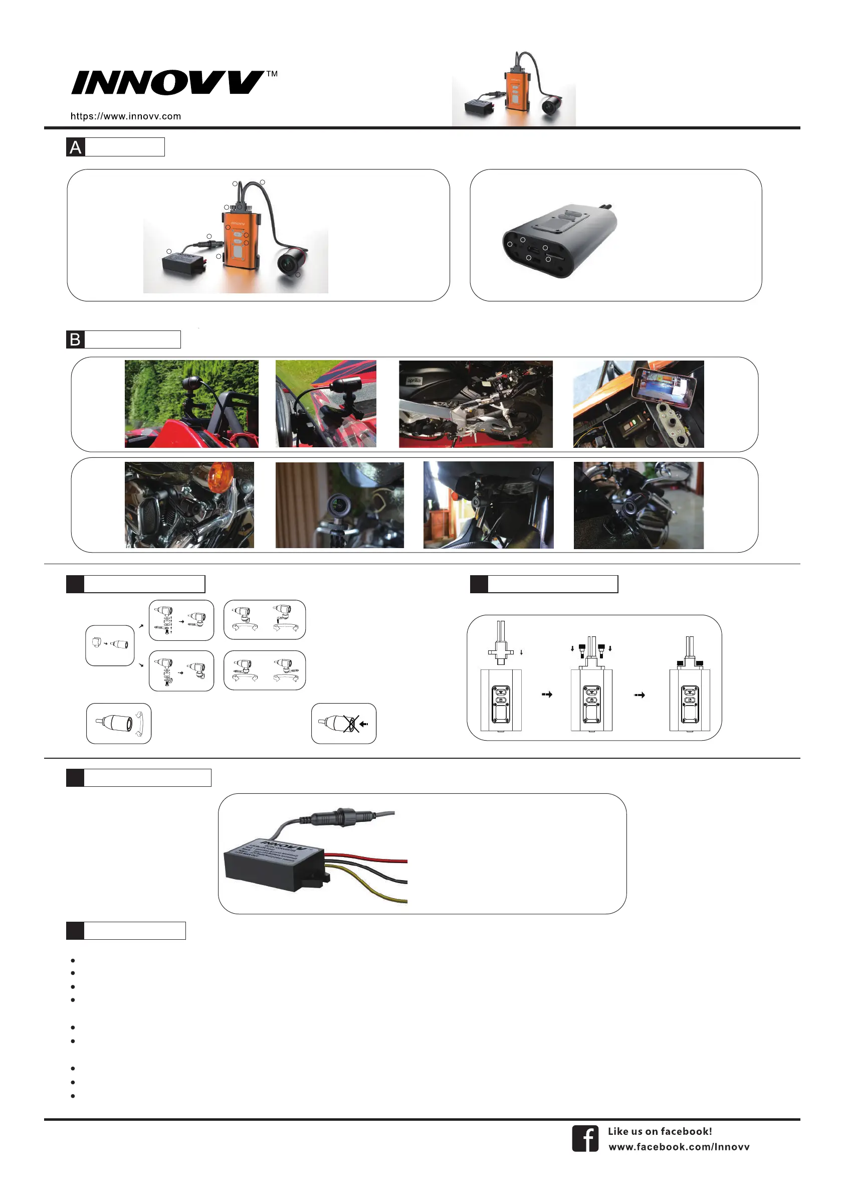
Product Over View
Installation Reference
Camera Bracket Installation
Do not push Lens!
1.DVR
2.WiFi Buon
3.Power Buon
5.Lens Cable
4.Lens
6.Power Cable
7.Lens Plug
8.Thumb Screw
9.Power Cable Connector
10.12V to 5V DC Converter
11.DVR Holder
12.External Mic
13.Internal Mic Hole
14.Mini USB Port
15. Reset Hole
16. SD card Slot
1
2
3
4
12
13
14
15
16
5
6
7
8
9
10
11
C
12V DC Converter Connection
E
Installation Instructions
F
Camera and DVR Connection
D
Locate a posion that will allow the best view.
Ensure the mount is secure and will not interfere with the operaon of the motorcycle. Consider the range of moon on the front forks of a motorcycle.
The camera may be mounted in several posions using the provided mounng accessories. Ensure you do not unscrew camera case or it may cause damage to lens inside.
Route the camera cable in a safe manor back to the DVR locaon. Ensure the cables are not subjected to a pinch point or in an area that will expose it to high temperature from the engine, and keep cable away
from all of the other cables (parcularly head light, tail light cables) to avoid EMI (Electro-Magnec Interference).
The C5 is designed to start/stop recording when the ignion is turned on/off.
The yellow wire from the supplied DC 12V to 5V converter is to connect the switched power source which has power only when the main ignion switch is on. Red wire is to connect the reliable and stable 12V
power source, like the posive terminal of baery. Black wire is to ground connecon.
Please keep a distance between DVR and Converter.
USB port beside of memory slot work as factory service port only, not for powering.
The C5 has an internal Mic to record audio. An external microphone (not included) can also be connected to the camera to record communicaons, etc.
Input Wires Connecon:
Red Wire: + (Posive Baery Terminal), Black Wire: - (Negave
Baery Terminal)
Yellow Wire: To 12V Switched Power Source, that is to trigger
power supply from power source to camera system when
ignion is on.
OUTPUT: DC 5V 2A (Max).
There is 10 second delay for ignion power on or power off.
Keep the INNOVV logo on the camera housing
face up (at the 12 o’clock posion) for correct
video orientaon.
Hold the lens house to adjust orientaon.
 Loading...