2 Wiring
2
- 30 -
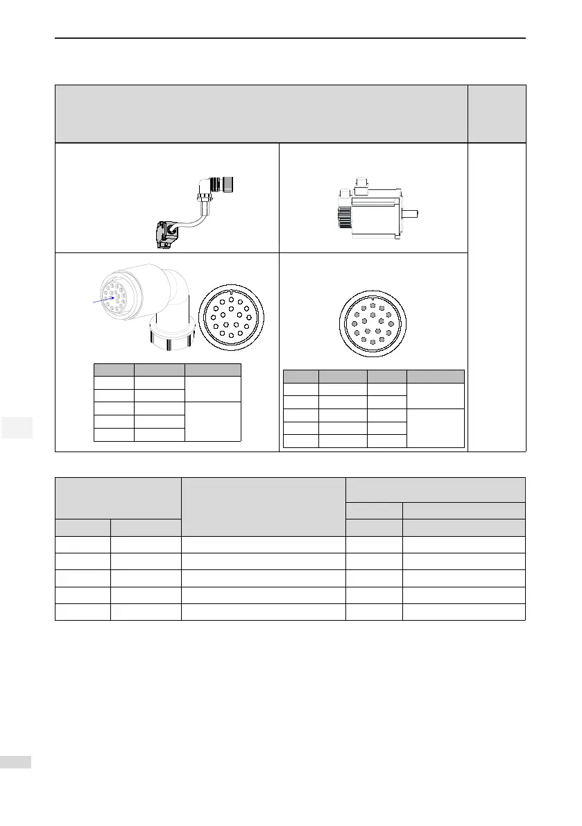
Table 2-11 Connectors of 20-bit encoder cables (MIL-DTL-5015 series 3108E20-29S military spec. plug)
Connector Appearance and Pin Layout
Frame Size
of Matching
Motor
Encoder cable
connector
Connect to CN2
of the drive
Encoder connection socket
100
130
180
20-29 military spec.
A
B
M
C
L
N
T
P
D
K
R
S
E
J
F
G
H
Pin No. Signal
A PS+
Twisted-pair
B PS-
G +5V
H GND
J Shielded
20-29 military spec.
A
M
B
L
C
N
P
T
K
D
S
R
J
E
H
G
F
Pin No. Signal Color
A PS+ Yellow
Twisted-pair
B PS- Blue
G +5V Red
H GND White
J Shielded
Table 2-12 Pin connection relation of IS620P series 20-bit encoder cables
DB9 on Servo Drive Side
Function Description
Motor Side
9-pin 20-29 Military Spec.
Signal Pin No. Pin No. Pin No.
PS+ 1 Serial communication signal + 3 A
PS- 2 Serial communication signal - 6 B
+5V 7 Encoder +5V power supply 9 G
GND 8 Encoder +5V power ground 8 H
PE Housing Shield 7 J
Observe the following precautions when wiring the encoder:
● Ground the servo drive and shielded layer of the servo motor reliably. Otherwise, the servo drive will
report a false alarm.
● Do not connect cables to the reserved pins.
● To determine the length of the encoder cable, consider voltage drop caused by the cable resistance
and signal attenuation caused by the distributed capacitance. It is recommended to use twisted-pair
cable of size 26AWG or above (as per UL2464 standard) and with a length within 10 m.
 Loading...