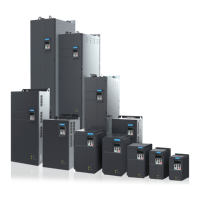
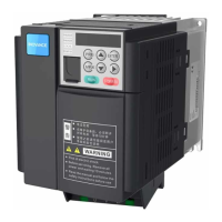
Do you have a question about the Inovance MD500T45GB-INT and is the answer not in the manual?
Emphasizes extreme care when working with the AC drive due to high voltages and lethal potential.
Details responsibilities for system design, installation, and maintenance for overall safety.
Highlights risks of electrical shock and safety precautions for installation.
Provides detailed electrical ratings including input, output, voltage, and frequency specifications.
Lists standard functions, control modes, speed ranges, torque control, and environmental specifications.
Specifies requirements for working temperature, cooling, ventilation, and mounting location.
Details correct mounting orientation and necessary clearances for different power ratings.
Describes backplate and through-hole mounting methods, including necessary steps and precautions.
Illustrates a typical wiring diagram showing connections for power, motor, and control signals.
Details terminal arrangements, functions, cable dimensions, and tightening torques for main circuits.
Explains terminal functions, wiring diagrams, and cabling requirements for control circuits.
Provides a checklist of essential items to verify before and during electrical installation.
Details the operating panel's keys, status indicators, and LED display functions.
Explains how the MF.K key can be configured via F7-01 to switch command sources or implement jogs.
Describes how to back up, restore, or initialize parameter settings using function FP-01.
Instructions on enabling, disabling, and setting a user-defined password for parameter protection.
Step-by-step guide for initial configuration, including wiring checks, parameter restoration, and motor setup.
Instructions to set motor nameplate parameters like power, voltage, current, frequency, and speed.
Guidance on performing static or dynamic auto-tuning to obtain motor parameters.
Setting F0-02 to select between operating panel, terminal I/O, or serial communication for control.
Setting F0-01 to choose between SVC, FVC, or V/F control modes.
Configures functions for digital input terminals (DI1-DI10) like RUN, JOG, or multi-reference.
Configures functions for digital output terminals (FM, Relay, DO1, DO2) like AC Drive running or Fault output.
Procedure for performing a trial run to check operation performance and troubleshoot issues.
Details three methods for controlling start/stop: operating panel, terminal I/O, and serial communication.
Explains four terminal I/O control modes (two-wire, three-wire) for controlling drive operation.
Covers communication protocols like Modbus-RTU, PROFIBUS-DP, CANopen, and CANlink.
Describes four methods for setting frequency reference: main, auxiliary, calculation, and command source.
Explains the PID control function for closed-loop control of variables like flow, pressure, or temperature.
Functions to limit torque for system protection, settable via F2 or A0 parameters.
Covers various protection functions including motor overload, phase loss, fault reset, and overvoltage.
Configuration for motor overload protection with inverse time-lag characteristics and pre-warning.
Settings for input and output phase loss protection, and fault protection action selection.
Defines actions for various faults like overload, phase loss, and user-defined faults.
Sets undervoltage, overvoltage thresholds and overcurrent fast prevention.
Provides overcurrent protection for the AC drive based on output current level and delay.
Enables multi-drive applications where drives are coupled by gear, chain, or conveyor belt.
Describes functions of Digital Input (DI), Digital Output (DO), Virtual DI/DO, AI, and AO terminals.
Details the allocation of 50 functions to ten DI terminals, including input resistance and voltage range.
Explains functions of FM, Relay, and DO terminals for outputting status and alarm information.
Covers communication links like Modbus, PROFIBUS-DP, CANopen, and CANlink for monitoring and control.
Explains communication addresses and protocols for reading and writing function parameters.
Describes the use of DI, DO, AI, and AO terminals, including filter time and delay functions.
Covers installing extension cards and setting F0-28 for serial communication protocols like Modbus, PROFIBUS-DP, CANopen, CANlink.
Classifies communication data into parameter and non-parameter data, defining addresses.
Details Modbus-RTU protocol for PC/PLC control, including bus structure, data format, and CRC check.
Provides selection guidance for MCCBs, fuses, and contactors based on MD500 model and rated current.
Guides the selection of braking resistor resistance, power, and typical braking frequencies for applications.
Provides a table for selecting braking units and resistors based on AC drive model and motor power.
Lists available extension cards for field bus, encoders, and user programming functions.
Covers CE mark, Low Voltage Directive compliance, and EMC guidelines.
Details EMC directive compliance (2004/108/EC, EN 61800-3) and system integrator responsibilities.
Addresses issues with leakage current causing circuit-breaker tripping and suggests solutions.
Provides solutions for common EMC problems like leakage protection tripping and I/O interference.
Explains de-rating requirements for carrier frequency, ambient temperature, and altitude.
Lists daily inspection items for motor, fan, installation environment, load, and input voltage.
Details items for periodic inspection, including general, cables, peripheral devices, ventilation, and control circuit.
Identifies wearing components like fans and electrolytic capacitors and provides service life information.
Essential safety precautions to follow before performing any troubleshooting or maintenance.
Provides solutions for common problems like oscillation, poor response, and noise during trial runs.
Explains how fault codes are displayed on the operation panel and the meaning of indicators.
Describes methods for resetting faults: through DI terminal, operating panel, automatic, or host computer.
Provides a table to troubleshoot faults based on operating panel display, cause, and possible solutions.
Lists common symptoms and their possible causes and solutions for diagnosis.
Lists standard parameters from groups F0, F1, F2, F3, F4, F5, F6, F7, F8, F9, FA, FB, FC, FD, FE, FF.
| Power | 45kW |
|---|---|
| Rated Power | 45 kW |
| Output Current | 90A |
| Cooling Method | Forced air cooling |
| Enclosure Rating | IP20 |
| Output Voltage | 0-480 VAC |
| Protection Features | Overvoltage, Undervoltage, Overcurrent, Short Circuit |
| Communication Interface | CANopen |
| Ambient Temperature | -10°C |
| Storage Temperature | -20~60°C |
| Humidity | 5% to 95% (non-condensing) |
| Altitude | Up to 1000 m |
| Input Voltage | 380-480 VAC |


 Loading...