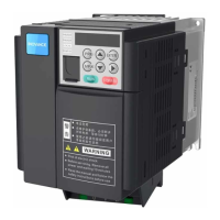
Do you have a question about the Inovance MD310 T0.7B and is the answer not in the manual?
Essential safety measures for working with the AC Drive, covering high voltages.
Guidelines for safe design, installation, and maintenance by trained personnel.
Precautions for electrical shock risks during installation and servicing.
Requirements for protective earthing and RCD usage to prevent shock.
Explains the model designation system for MD310 AC Drives.
Details the information presented on the AC drive's nameplate.
Provides detailed technical specifications like frame size, dimensions, input/output ratings.
Illustrates the standard wiring connections for a three-phase 380 VAC power supply.
Lists and describes main circuit and control circuit terminals for the AC drive.
Specifies wire sizes and tightening torques for control circuit connections.
Explains how to cut the EMC jumper or remove the EMC screw for leakage current reduction.
Discusses grid system requirements and EMC screw removal for specific models.
Presents a complete timing diagram illustrating the drive's operational logic.
Provides a flowchart for the step-by-step setup process of the AC drive.
Lists common fault codes, their possible causes, and recommended solutions.
Guides users through diagnosing common operational symptoms and potential issues.
Details standard parameters (Group F0) for drive configuration and operation.
Lists parameters available for monitoring the drive's operational status and values.
| Power | 0.75 kW |
|---|---|
| Control Mode | V/F Control, Sensorless Vector Control |
| Overload Capacity | 150% for 60 seconds |
| Switching Frequency | 2-16 kHz |
| Enclosure Rating | IP20 |
| Operating Temperature | -10°C to +50°C |
| Storage Temperature | -20°C to +60°C |
| Protection Features | Overcurrent, Overvoltage, Undervoltage, Overheat, Short Circuit |
| Communication Interface | RS485, Modbus RTU |
| Cooling Method | Air Cooling |


