© Copyright 2016 InPower LLC
DBT-MD-01 Owner’s Manual
4
Document: OM-194 Version Code: A
Date: August 2016 Date: Sept. 14, 2016
2.3 Mounting
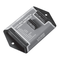
Mount the DBT-MD module under the dash or on a at surface using the two
mounting holes. Ensure that you have sufcient distance to install the 36 inch
OBD-II cable that is part of the J2 harness.
Plug the J1 cable into the J1 connector (20 pin connector) and plug the J2
cable into the J2 connector (12 pin connector). The J2 cable will be used
for the OBD-II connection, power input, RPM adjustment and hooking up
either remote RPM or PWM. The J1 cable will be used for hooking into the
SEIC circuit, high idle on/off or mode select switches and for providing output
signals.
2.4 Wiring
Ensure the J1 cable and the J2 cables are both connected to the module.
Note: So long as the vehicle is on and the unit has power, even if the
High Idle Throttle function is not engaged, the Databus Decoder signals
will continue to operate. If the Databus Decoder signals will not be used,
properly secure the Output wire group on the J1 harness.
A. OBD-II connector
Locate the red connector on the J2 harness. Route this portion of the cable
to the OBD-II Data Link Connector and plug it in. The OBD-II connector is
usually located on the lower part of the dash on the driver’s side. Using a
plastic cable tie, secure the plug to the OBD-II connector so that it will not
vibrate out. We recommend routing the DLC cable across the bottom of the
plug and looping the cable tie around the plug, socket and cable to keep it out
of the way.
B. SEIC
Locate the SEIC group of blunt cut wires on the J1 harness. Install wires
between the blunt cut wires provided on the J1 harness and the respective
inputs and outputs of the Ford SEIC as shown in the wiring diagrams.
C. High Idle Mode Selection Controls
Determine the combination of high idle speed modes you will need (standby
high idle, variable RPM control and/or up to two additional xed preset
speeds).


 To Next Page