Do you have a question about the Insportline HG3060 and is the answer not in the manual?
Connects straight base (C) to joint base (A) using specific fasteners.
Joins joint tube (B) to straight base (C) for structural integrity.
Mounts swivel pulley block I (O) onto the joint base (A).
Secures the upright frame (D) and guide rod (H) to the base.
Connects swivel pulley block II (P) to the adjustment tube (E).
Connects the joint rod (L) to the joint base (A).
Slides washer (5) and donut (3) onto the guide rod (H).
Places weight plate (T) onto guide rod (H) and secures selector rod (U).
Attaches bushing (V) and pin (W) to selector rod (U).
Joins joint beam (K) to straight beam (G) with pulleys and fasteners.
Connects straight beam (G) to upright frame (D) and guide rod (H).
Attaches top joint tube (I), pulleys (1, 2) to straight beam (G).
Mounts swivel pulley block III (Q) to the top cross beam (J).
Connects top cross beam (J) to top joint tube (I) and joint beam (K).
Attaches joint rod (L) to the top cross beam (J).
| Product Name | Insportline HG3060 |
|---|---|
| Category | Fitness Equipment |
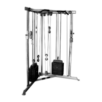
| Type | Multi-gym |
| Resistance Type | Weight stack |
| Warranty | 2 years |
| Resistance Levels | Not adjustable |
| Display | No |