Intel
®
Desktop Board D915GVWB Specification Update
7
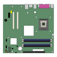
3. The placement of capacitors behind the PCI Express* x1
connector slot may prohibit some PCI Express x1 add-in
cards from properly connecting to the motherboard.
PROBLEM: Due to the design and placement of the audio circuitry on this motherboard, it was necessary to
position capacitors in the keep-out zone behind the PCI Express* x1 connector slot.
IMPLICATION: Some PCI Express x1 add-in cards may not fully connect to the PCI Express x1 connector slot,
due to interference between capacitors in the keep-out zone and I/O connectors on the add-in card that are
located on the I/O bracket, in line with the edge fingers on the card.
WORKAROUND: None
STATUS: MAY BE FIXED IN A LATER HARDWARE REVISION.