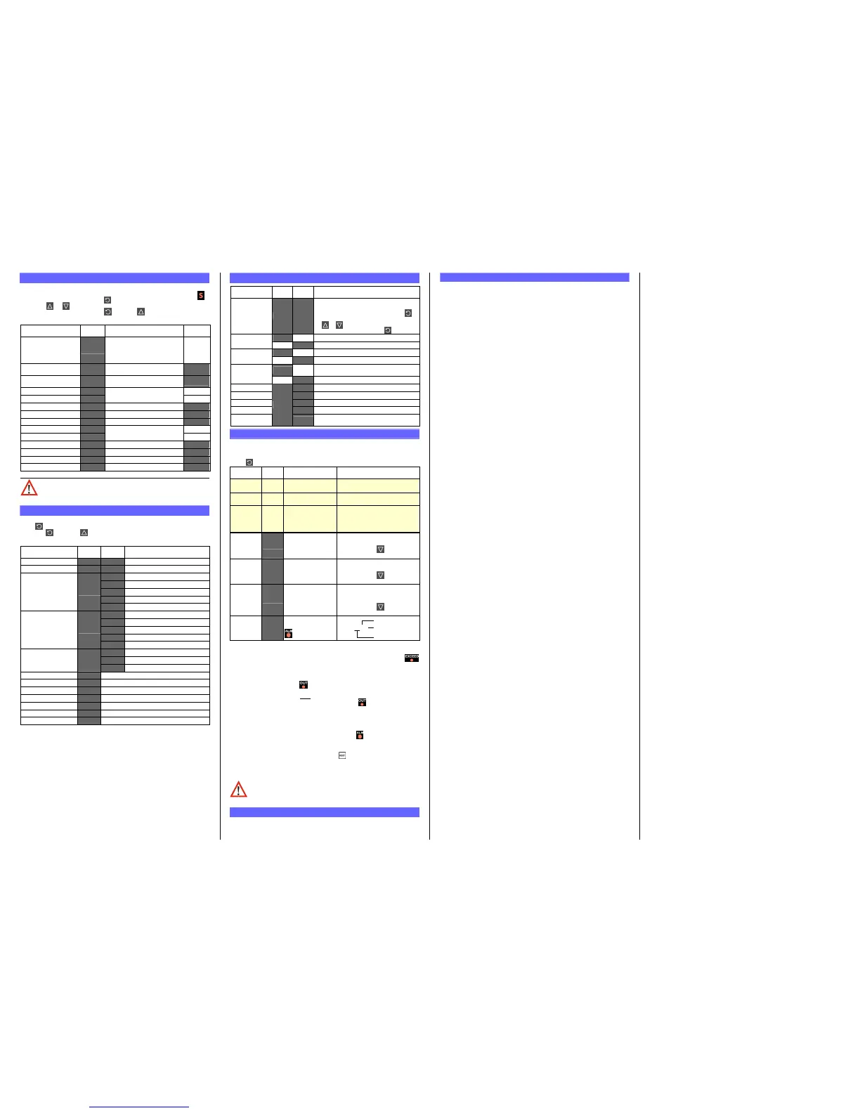
4. SETUP MODE
Note: Configuration must be completed before adjusting Setup parameters.
First select Setup mode from Select mode (refer to section 2). The Setup LED
will light while in Setup mode. Press to scroll through the parameters,
then press or to set the required value.
To exit from Setup mode, hold down and press to return to Select mode.
Note: Parameters displayed depends on how instrument has been configured.
Parameter Lower
Display
Upper Display Adjustment
Range & Description
Default
Value
Limit Setpoint value
Scaled Range Minimum to
scaled Range Maximum
R/max if
=
R/min if
=
Limit Hysteresis
*
**
*
1 LSD to full span in display units,
on the safe side of the limit SP
Input Filter Time Constant
OFF or 0.5 to 100.0 secs
(see CAUTION note below)
.
High Alarm 1 value
R/max
Low Alarm 1 value
Scaled Range Minimum to
scaled Range Maximum
R/min
Deviation Alarm 1 Value
±Span from SP in display units
Band Alarm 1 value
1 LSD to span from setpoint
Alarm 1 Hysteresis
!
!!
!
1 LSD to full span in display units
High Alarm 2 value
R/max
Low Alarm 2 value
Scaled Range Minimum to
scaled Range Maximum
R/min
Deviation Alarm 2 Value
±Span from SP in display units
Band Alarm 2 value
1 LSD to span from setpoint
Alarm 2 Hysteresis
!
!!
!
1 LSD to full span in display units
Setup Lock Code
)
))
)
0 to 9999
Note: Operator mode screens follow, without exiting from Setup mode.
CAUTION: An excessively large filter time could significantly delay
detection of a limit condition. Set this value to the minimum required
to remove noise from the process variable
5. PRODUCT INFORMATION MODE
First select Product information mode from Select mode (refer to section 2).
Press to view each parameter. To exit from Product Information mode,
hold down and press to return to Select mode.
Note: These parameters are all read only.
Parameter Lower
Display
Input type
%
%%
%
#
##
#
Universal input
Option 1 type (fixed)
*
**
*
Latching Limit Relay
No option fitted
*
**
*
Relay output
SSR drive output
Triac output
Option 2 module type
fitted
Linear DC voltage / current output
No option fitted
*
**
*
Relay output
SSR drive output
Linear DC voltage / current output
Option 3 module type
fitted
No option fitted
&
&&
&
RS485 communications
Auxiliary Option A
module type fitted
Digital Input for remote reset
Firmware type
+,
+,+,
+,
Value displayed is firmware type number
Firmware issue
%$$
%$$%$$
%$$
Value displayed is firmware issue number
Product Revision Level
Value displayed is Product Revision level
Date of manufacture
Mm
MmMm
Mm
Manufacturing date code (mmyy)
Serial number 1
First four digits of serial number
Serial number 2
Middle four digits of serial number
Serial number 3
Last four digits of serial number
6. ERROR/FAULT INDICATIONS
Parameter Upper
Display
Configuration & Setup required. This screen is
seen at first turn on, or if hardware
configuration has been changed. Press to
enter the Configuration Mode, next press
or to enter the unlock code number,
Process variable input > 5% over-range
as above if Display Strategy =
-
--
-
.
..
.
Process variable input > 5% under-range
as above if Display Strategy =
/
//
/
Break detected in process variable input
sensor or wiring
Input Sensor
Break
Normal
as above if Display Strategy =
Option 1 Error
Option 2 Error
Option 3 Error
Option A Error
Option A module fault
Option B Error
Option B not used on Limit Controllers
this error is shown if any module is fitted
7. OPERATOR MODE
This mode is entered at power on, or accessed from Select mode (see section 2).
Note: All Configuration mode and Setup mode parameters must be set as
required before starting normal operations.
Press to scroll through the parameters.
Upper
Display
Lower
Display
Value
=
(initial screen)
PV and Limit Setpoint values
=
(initial screen)
Limit Setpoint value
or
(Blank)
or PV
Value
=
.
(Initial Screen)
Displays
and PV if Limit
Output is active or
and blank
if not active.
High Limit
Hold
=
Highest PV value since this
parameter was last reset.
To reset, press for 5 seconds,
display =
0000
when reset
Low Limit
Hold
=
Lowest PV value since this
parameter was last reset.
To reset, press for 5 seconds,
display =
0000
when reset
Value
Always available
Format
then mmm.s
(10 sec increments)
Shows
-
--
-
.
..
.
if 999.9
Accumulated time of Limit SP
exceed conditions since this
parameter was last reset.
To reset, press for 5 seconds,
display =
0000
when reset
Active Alarm
Status
When one or more
alarms are active.
ALM indicator
will also flash
L
Alarm 2 active
Alarm 1 active
L
Annunciator active
Exceed Condition
An Exceed Condition is when the Process Variable exceeds the Limit Setpoint value
(i.e. PV > SP when set for high limit action, PV < SP for low limit action). The
LED is on during this condition, and is extinguished once it has passed.
Limit Output Function
Limit Output relay(s) de-energise whenever an Exceed condition occurs, causing
the process to shut down. The LED is on when the relay is de-energised.
The relay remains latched off even if the Exceed condition is no longer present.
Only giving a reset instruction (after
the exceed condition has passed) will re-
energise the relay, allowing the process to continue. The LED then turns off.
Limit Annunciator Outputs
An Annunciator output will activate when an Exceed condition occurs, and will
remain active until a reset instruction is received, or the Exceed condition has
passed. Unlike the Limit Output, an Annunciator can be reset even if the Exceed
condition is present. When an Annunciator is active, the LED will flash and the
Alarm Status screen is available.
Resetting Limit Outputs & Annunciators
A reset instruction can be given by pressing the key, via the Digital Input (if
fitted) or via a Comms command if an RS485 Communications module is fitted.
Annunciators will deactivate. Limit Outputs will only re-energise if the Exceed
condition has passed.
CAUTION: Ensure that the cause of the Exceed condition has been
rectified before resetting the Limit Output.
8. SERIAL COMMUNICATIONS
Refer to the full user guide (available from your supplier) for details.
9. SPECIFICATIONS
UNIVERSAL INPUT
Thermocouple
Calibration:
±0.1% of full range, ±1LSD (±1°C for Thermocouple CJC).
BS4937, NBS125 & IEC584.
PT100 Calibration:
±0.1% of full range, ±1LSD.
BS1904 & DIN43760 (0.00385
Ω
/
Ω
/°C).
DC Calibration:
±0.1% of full range, ±1LSD.
Sampling Rate: 4 per second.
Impedance:
>10MΩ resistive, except DC mA (5Ω) and V (47kΩ ).
Sensor Break
Detection:
Thermocouple, RTD, 4 to 20 mA, 2 to 10V and 1 to 5V ranges
only. Limit outputs turn off (goes into Exceed condition), high
alarms activate for thermocouple/RTD sensor break, low
alarms activate for mA/V DC sensor break.
Isolation: Isolated from all outputs (except SSR driver).
Universal input must not be connected to operator accessible
circuits if relay outputs are connected to a hazardous voltage
source. Supplementary insulation or input grounding would
then be required.
DIGITAL INPUT
Volt-free(or TTL): Open(2 to 24VDC) =No Reset.
Closed(<0.8VDC) = Reset (edge triggered).
Isolation: Reinforced safety isolation from inputs and other outputs.
OUTPUTS
Limit Relay
Contact Type &
Rating:
Latching limit control relay. Single pole double throw (SPDT);
5A resistive at 120/240VAC. Slot 1 position fixed for this
function, optional function for Slot 2 & 3 relay modules,
Lifetime: >100,000 operations at rated voltage/current.
Isolation: Basic Isolation from universal input and SSR outputs.
Alarm Relays
Contact Type &
Rating:
Slot 2 or 3 position non-latching alarm relay.
Single pole double throw (SPDT); 2A resistive at 120/240VAC.
Lifetime: >500,000 operations at rated voltage/current.
Isolation: Basic Isolation from universal input and SSR outputs.
SSR Driver
Drive Capability:
SSR drive voltage >10V into 500Ω min.
Isolation: Not isolated from universal input or other SSR driver outputs.
Triac
Operating Voltage: 20 to 280Vrms (47 to 63Hz).
Current Rating: 0.01 to 1A (full cycle rms on-state @ 25°C);
derates linearly above 40°C to 0.5A @ 80°C.
Isolation: Reinforced safety isolation from inputs and other outputs.
DC
Resolution: 8 bits in 250mS (10 bits in 1s typical, >10 bits in >1s typical).
Isolation: Reinforced safety isolation from inputs and other outputs.
Transmitter PSU
Power Rating:
20 to 28V DC (24V nominal) into 910Ω minimum resistance.
Isolation: Reinforced safety isolation from inputs and other outputs.
SERIAL COMMUNICATIONS
Physical: RS485, at 1200, 2400, 4800, 9600 or 19200 bps.
Protocols: Selectable between Modbus and West ASCII.
Isolation: Reinforced safety isolation from all inputs and outputs.
OPERATING CONDITIONS (FOR INDOOR USE)
Ambient
Temperature:
0°C to 55°C (Operating), –20°C to 80°C (Storage).
Relative Humidity: 20% to 95% non-condensing.
Supply Voltage and
Power:
100 to 240VAC ±10%, 50/60Hz, 7.5VA
(for mains powered versions), or
20 to 48VAC 50/60Hz 7.5VA or 22 to 65VDC 5W
(for low voltage versions).
ENVIRONMENTAL
Standards: CE, UL, ULC & FM 3545, 1998
EMI: Complies with EN61326 (Susceptibility & Emissions).
Safety
Considerations:
Complies with EN61010-1 & UL3121.
Pollution Degree 2, Installation Category II.
Front Panel Sealing:
To IP66 (IP20 behind the panel).
PHYSICAL
Front Bezel Size:
1
/
16
Din = 48 x 48mm,
1
/
8
Din = 96 x 48mm,
1
/
4
Din = 96 x 96mm.
Depth Behind Panel:
1
/
16
Din = 110mm, ,
1
/
8
&
1
/
4
Din = 100mm.
Weight: 0.21kg maximum.
 Loading...


