Do you have a question about the intellic Bosch EFAS-4.10 and is the answer not in the manual?
Identifies the intended audience for the workshop manual, including authorized personnel for installation and calibration.
Explains the meaning of special symbols used throughout the workshop manual for emphasis and warnings.
Details key EU regulations binding on member states for driver working conditions and tachograph use.
Covers provisions for international road transport crews outside the European Union.
Highlights the need to adhere to national legislation supplementing EU regulations.
Lists standards and regulations that the EFAS Smart Tachograph complies with.
Explains the transition to second-generation smart tachographs and card requirements.
Details vehicles exempted from the compulsory installation of smart tachographs in Europe.
Describes the components and data stored by smart recording equipment.
Provides an overview of tachograph smart-cards, their types, and functions.
Overview of the EFAS smart tachograph's features, activation conditions, and shutdown.
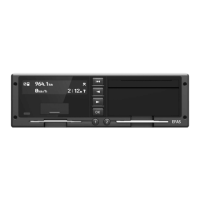
Details the functions of the six operating keys on the front of the EFAS device.
Explains the two card reader slots and their mechanical and electrical operation.
Describes the EFAS tachograph's alphanumeric monochrome graphics-capable LCD display.
Summarizes the meanings of the red warning light and acoustic signals indicating operational states.
Explains the printer paper container and how to refill it with a new paper roll.
Details the front panel service port, including calibration and download interfaces.
Guides users on navigating menus and making selections using the operating keys.
Explains the four types of smart-cards and their effect on the tachograph's operating mode.
Covers essential preparations before installing the EFAS smart tachograph in a vehicle.
Explains the information provided on the EFAS type label, including hardware and software versions.
Details different hardware and software versions of the EFAS device and previous revisions.
Outlines checks for type label and seals to ensure no tampering before installation.
Provides guidelines for handling and installing the EFAS tachograph in a standard car radio bay.
Describes the connector panel layout and pin assignments for connecting the tachograph.
Details the pin assignments for plug connectors A, B, C, and D of the EFAS device.
Explains the EU regulations, installation, and pairing process for the motion sensor.
Guides on securely mounting the EFAS tachograph unit in the vehicle.
Details the signals that activate the EFAS tachograph and its operating states.
Provides instructions for replacing the internal buffer battery, including precautions.
Covers pre-activation steps like battery replacement and software checks.
Guides through the activation process, including switching on and pairing with sensors.
Explains how to manually initiate motion sensor pairing if automatic pairing fails.
Describes the installation and connection of the DSRC module for remote communication.
Explains how to adjust the internal clock settings, including date, time, and time zone.
Details the process for setting the date and time, including UTC and local time adjustments.
Covers setting the time zone offset to display local time correctly.
Explains how to configure automatic switching between daylight saving and standard time.
Allows selection between DD.MM.YYYY and DD/MM/YYYY date formats.
Enables pre-programmed activity settings for drivers when ignition is turned on or off.
Describes the irreversible function to block or reject first-generation tachograph cards.
Explains how to switch the remote data download function on or off.
Lists functions available when the FMS unit is attached and activated.
Provides step-by-step instructions for replacing the printer paper roll.
Explains that parameters can be read out in any mode, but changes require authorization.
Defines parameter value ranges as per ISO 16844-7 and their fixed lengths.
Lists key parameters for adapting the tachograph to vehicle types and external devices.
Describes the function that automatically sets some parameters based on input signals.
Details legally prescribed vehicle parameters preset to default values in the device.
Covers essential checks before calibration, including visual inspection and seal checks.
Specifies requirements for suitable test equipment certified for calibrating the EFAS tachograph.
Guides through the calibration process, including pre-checks and test runs.
Details the procedure and requirements for conducting a test drive for calibration purposes.
Explains the purpose and required details for the installation plaque affixed to the vehicle.
Explains how the tachograph monitors system functions and differentiates events from malfunctions.
Describes the three types of error codes: EFT, DTC, and Service ID.
Details how events and malfunctions are displayed in different operating modes.
Provides a general approach to checking and resolving displayed or stored faults.
Introduces test equipment and the EFAS Service Tool for fault diagnosis and configuration.
Lists the built-in test functions for operating components and hardware diagnostics.
Explains how to perform a printer test to check print quality and functionality.
Notes that EFAS checks card condition during operation; errors are identified by DTCs.
Details optical inspection of the display for pixel control and quality.
Describes manual operation of keys to detect blocked keys or contact problems.
Reports general hardware faults and associated DTC error codes.
Explains how to check the engine speed detection configuration and sources.
Guides on checking the on-board power supply voltage at connector A1.
Inspects digital inputs and outputs at the EFAS connector socket for wiring and signal levels.
Verifies the calculated rotational speed of the output shaft based on sensor pulses.
Checks voltage, current, and pulse frequency for the motion sensor interface.
Performs a check on the internal back-up battery voltage.
Checks the functionality of pulse outputs B6, B7, B8, and D6.
Indicates whether the GNSS function is operating correctly.
Tests the functionality of the remote communication equipment, the DSRC module.
Allows checking CAN bus communication on CAN A and CAN C using the EFAS Service Tool.
Step-by-step guide on how to safely remove the EFAS tachograph from the vehicle.
Instructions for removing a smart-card that cannot be ejected from its slot.
Refers to section 6.2.6 for detailed instructions on replacing the buffer battery.
Specifies repairs that must be performed by the manufacturer or dealer.
Outlines procedures for decommissioning a tachograph, including data download and disposal.
Details the manufacturer's warranty period and conditions for the EFAS device.
Lists circumstances that invalidate the device's warranty.
Provides an overview of Event Fault Types (EFT) specified for smart tachographs.
Lists all events and faults with their meanings and troubleshooting measures.
Lists Diagnostic Trouble Codes (DTCs) and their corresponding Service IDs for the tachograph system.
Explains how to print or display the last 100 service IDs from the EFAS menu.
Guides on creating a support file using the EFAS Service Tool for troubleshooting.
Provides an overview of CAN interfaces, data transfer types, and relevant parameters.
Explains the necessity and configuration of CAN bus terminating resistors.
Details the types of data transferred via CAN bus, including cyclic and requested data.
Lists parameters for configuring CAN buses to meet specific vehicle type requirements.
Describes the bidirectional serial ports D7 and D8 and their potential uses.
Details the info-interface protocol for cyclical data transmission.
Explains the K-line interface for diagnostics and parameter reading.
Covers EFAS pulse outputs used for controlling external displays.
Explains how EFAS codes travel speed as a function of input pulse frequency.
Details the selection of speed calculation methods for output D6.
Describes the output encoding for distance travelled, providing one pulse per 0.25 m.
Explains how vehicle speed is recorded in groups with selectable range limits.
Details the recording of engine speed from pulse signals or CAN bus.
Describes how status changes at inputs D1 and D2 are logged with timestamps.
Lists necessary items for software updates: computer, serial cable, EFAS Service Tool, and smart-card.
Explains how to display hardware and software versions using the menu or Service Tool.
Guides on requesting and downloading the latest tachograph software from the manufacturer.
Details the process of loading the tachograph software into the device using the EFAS Service Tool.
Covers post-update checks, potential failure causes, and re-calibration requirements.
Provides symbols for persons, their activities, and the tachograph's operating modes.
Presents symbols used to identify different types of tachograph smart-cards.
Lists symbols representing various driver activities and their durations.
Shows symbols used for identifying different components of the tachograph system.
Details symbols representing specific conditions like 'Recording equipment not required'.
Provides pictograms for miscellaneous items such as events, malfunctions, and security.
Lists symbols used to represent various error messages related to smart-cards.
Shows symbols representing different time intervals like daily, weekly, and fortnightly.
Explains combinations of symbols for various functions and events.
Provides symbols related to driving activities, including team and day/week driving times.
Lists symbols used to denote different types of printouts from the tachograph.
Shows symbols representing common event messages encountered by the tachograph.
Lists symbols used to indicate various malfunctions detected by the tachograph.
Explains symbols used for marking manual entries of driver activities and locations.
Details messages displayed by the printer during operation, such as 'No paper'.
| Brand | intellic |
|---|---|
| Model | Bosch EFAS-4.10 |
| Category | Measuring Instruments |
| Language | English |