FrOnt/tOp panEl
The front- or top-panel LED indicators — POWER, Link/Act — allow for
more convenient monitoring and troubleshooting of the switch. The table
below shows each LED function.
rEar/sidE panEl
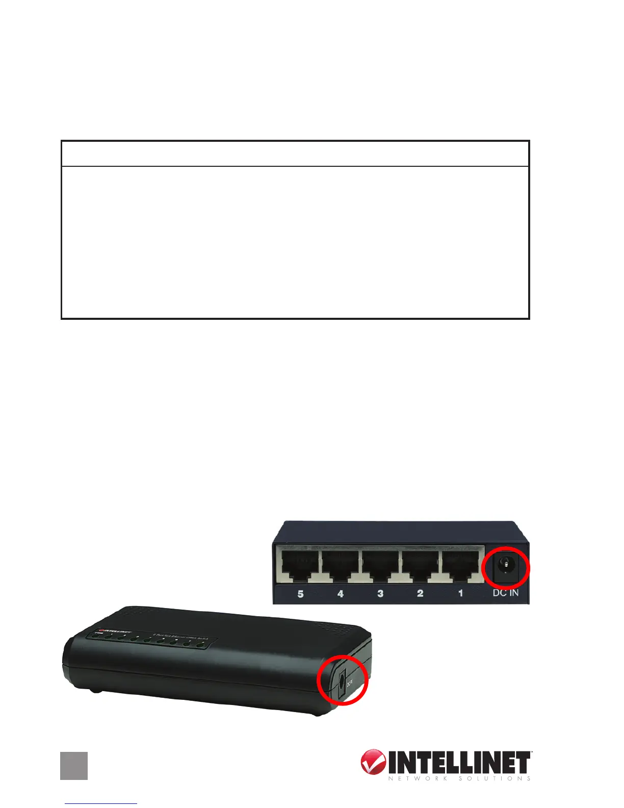
Power
Plug the female end of the power adapter rmly into the receptacle (on
the rear panel of Models 502023, 523301 and 523318; on the side panel
of Model 502054) and the other end into an electrical outlet. Conrm
that the power LED is lit for a normal power status. NOTE: To ensure
proper operation, use only the power adapter included with this switch.
4
LED Status Operation
POWER Steady green Power on
Off Check AC connection; turn the
power on
LINK/ACT Steady green Valid port connection
Blinking green Valid port connection; data being
transmitted/received
Off No link established
Power adapter jack:
Model 523301 (above);
Model 502054 (left)
 Loading...