IntelliTempc T-1000 INSTALLATION INSTRUCTIONS
The IntelliTemp Model T-1000 is designed to continually monitor, and
provide an accurate measurement of the ambient temperature.
The T-1000 allows the user to set high and low temperature parameters.
If the ambient temperature rises above or falls below the set parameter,
the T-1000 will signal a control panel or other monitoring device via Form-
A relays. Separate LEDs indicate whether the unit was tripped by tem-
peratures above or below the set parameters.
The Model T-1000 features a bright, three-digit display unit, which can be
set to display the temperature in degrees Fahrenheit or Celsius.
The T-1000 also includes a remote temperature probe, which can be
used to monitor remote locations
(up to 100 feet from the display unit)
while keeping the display unit in a convenient viewing location. If local
temperature monitoring is desired (monitoring the ambient temperature
surrounding the display unit), the remote temperature probe can be
installed inside the display unit.
MOUNTING LOCATION
The T-1000 is designed to be wall mounted in an environment where the
temperature ranges between 32° to 140° F (0° to 60° C). To monitor
temperatures beyond this range, use the remote temperature probe.
The temperature probe is designed to monitor a temperature environ-
ment between -40° to 140° F (-40° to 60° C).
The temperature probe comes with 15 feet of two conductor cable and
can be mounted at any desired location. The cable can be lengthened
(up to 100 feet) with any 22 AWG twisted pair wire.
IMPORTANT: If it is necessary to install more than one T-1000, make
sure that the serial numbers on the back of each temperature probe and
display unit match.
MOUNTING PROCEDURE
To open the display unit, insert a flat tip screwdriver into the slot on the left
side of the housing and depress the latch. Gently pull apart the front and
rear housing.
Inside the rear housing is the display unit printed circuit board (PCB) and
two mounting holes. Use the rear housing as a template to mark the
mounting holes on the wall. Drill the holes and use two of the screws
provided to secure the display unit to the wall.
NOTE: It is not necessary to remove the PCB from the rear housing
before mounting.
Using the temperature probe remotely:
Use the two remaining screws or double-sided foam tape to mount the
probe at the desired location. The cable between the temperature probe
and the main display unit can be lengthened up to 100 feet using 22
AWG twisted pair wire.
Using the temperature probe locally:
Install the temperature probe PCB onto the display unit PCB as described
below.
1. Push in the latches on the back side of the temperature probe hous-
ing using a flat tip screwdriver. Separate the front and rear housing, see
Figure 2.
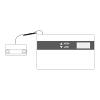
HIGH
LOW
Figure 1
T-1000 Top Housing Removed
2. Gently pull the PCB from the rear housing.
3. Cut off the plastic wire tie securing the cable to the PCB. Cut off the red
and black wires from the back side of the PCB as close as possible.
4. Place the temperature probe PCB into the display unit as shown in
Figure 3. Push the temperature probe PCB onto the pins of the display
unit PCB.
LO
HI
V-
NC
C
C
NC
V+
PROBE
TB1
-
+
E2
E1
J2
J1
HI
LO
F
C
POTENTIOMETERS
TEMPERATURE PROBE
MOUNTING PINS
TEMP
TRANSDUCER
MOUNTING
HOLE
MOUNTING
HOLE
LATCH
WIRE
KNOCKOUTS
R45 R12 R5
DO NOT
ADJUST
Figure 2
Temperature Probe Housing
V-
NC
C
V+
TB1
Remove Wire Tie
Temperature Probe PCB
Mounting Pins
Figure 3
Temperature Probe PCB