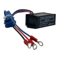
Isolator Relay Delay/E
Service Manual
The Battery Isolator Relay Delay/E is a reliable approach to
charging multiple batteries on a vehicle. It provides a delay
to allow the engine to briey “warm up” and to recharge the
main battery before placing the heavy load of a discharged
auxiliary battery on the alternator. It also allows the use of
self-exciting aternators.
How It Works
Isolator Function
The unit operates as an isolator by sensing the level of
voltage on the chassis 12 volt system. When this voltage
goes above 13.3 volts for approximately 12 seconds, as
happens when the engine is running normally (normal
alternator output voltage is approximately 14.4 volts), it will
close the isolator relay providing charging current to the
coach battery. When the ignition switch is turned off, the relay
will open immediately.
If the voltage should fall below 12 volts for more than two
seconds while the ignition is on, the relay will drop out to
feed all the alternators available output to the chassis battery
to keep the engine running. This might happen when the
alternator is not able to supply sufcient current to all of
the loads. When the chassis voltage goes above 13.3 volts
again, the relay will again close in about two seconds to retry
and charge the coach battery. The resultant ickering of lights
would alert the driver of the system overload.
Trouble Shooting
Problem
Coach battery not charging
Possible Cause / Solution
With engine running, chassis voltage must be above 13.5
volts (Blue wire) If less 13.3 volts, check vehicle’s charging
system
Check ground on module (Black wire)
Check for voltage on coil of isolator relay after engine has
been running for at least 20 seconds. (Red wire). Voltage
should be approximately 12 volts. If no voltage, replace
IRD/E.
If 12 volts is applied to isolator relay coil, check
for voltage drop across the isolator relay
contacts. If the drop is greater than 0.3 volts,
replace relay.
Problem
Chassis battery continues to drain
Possible Cause / Solution
Check voltage on module with ignition off. (Red and Blue
wire) should be 0 volts. If not, check wiring.
Check for continuity across the isolator relay contacts, the
relay should be open with no voltage applied to coil.
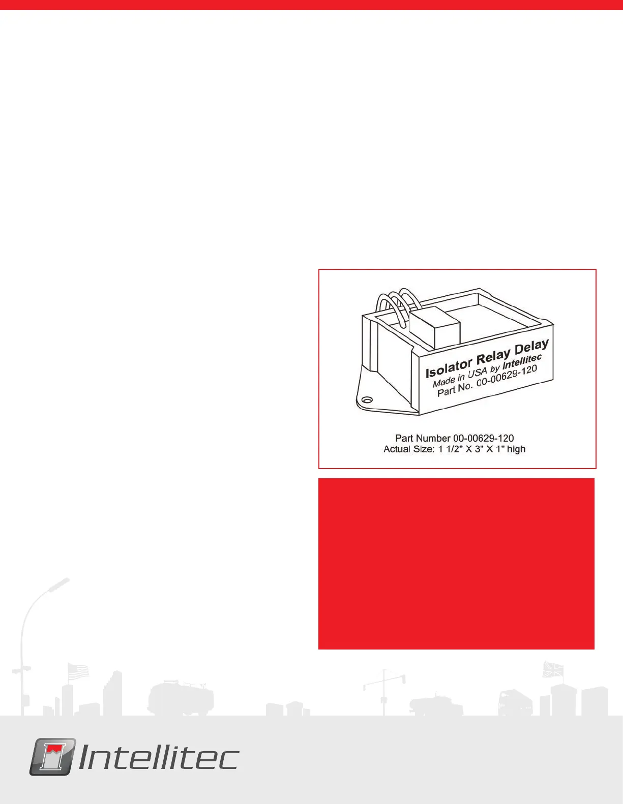
CAUTION:
The Isolator Relay Delay/E controls the Isolator Relay
which is connected directly to the chassis and coach
batteries. Power from both the batteries is fed into the
module. The full power of the battery is available at this
module. Inadvertant shorts at this box could result in
damage and/or injury.
All servicing of this module should be done only by a
qualied Service Technician
Tools required: Low current Test Light, Accurate
Voltmeter (digital read-out preferred)
 Loading...