Do you have a question about the Intellitec 00-00629-120 and is the answer not in the manual?
Explains the unit's low-cost, reliable approach to charging multiple batteries and its operational principles.
Details voltage, current, and temperature ratings for both 12V and 24V versions of the Isolator Relay Delay.
Provides guidance on diagnosing and resolving common problems like coach battery not charging or draining.
The Intellitec Isolator Relay Delay/E is a device designed to manage the charging of multiple batteries in a vehicle, offering a reliable and cost-effective alternative to diode isolators. Its primary function is to ensure that the main battery receives adequate charge before the auxiliary battery is connected, thereby preventing the heavy load of a discharged auxiliary battery from immediately taxing the alternator. This design also supports the use of self-exciting alternators and allows the engine to warm up briefly before the auxiliary battery is engaged. The unit is available in both 12-volt and 24-volt versions to accommodate different vehicle electrical systems.
The Isolator Relay Delay/E operates by continuously monitoring the voltage of the main battery system. When the engine is running and the alternator is producing its normal output voltage (typically around 14.4 volts for a 12-volt system), the main battery voltage will rise. The device is programmed to detect when this voltage exceeds 13.3 volts (or 26.6 volts for a 24-volt system) and maintains this level for approximately 12 seconds. This delay ensures that the engine has warmed up and the main battery has begun to recharge before the auxiliary battery is introduced into the charging circuit.
Once the voltage threshold and delay period are met, the Isolator Relay Delay/E activates, sending power to the coil of a conventional continuous duty cycle isolator relay. This relay then closes, allowing charging current to flow from the alternator to the auxiliary battery. This intelligent control prevents the alternator from being immediately overloaded by a heavily discharged auxiliary battery, which could potentially strain the engine or reduce the alternator's lifespan.
A key feature of this system is its ability to protect the engine and main battery from excessive discharge. If, while the engine is running, the main battery voltage drops below 12.0 volts (or 24 volts for a 24-volt system) for more than two seconds, the Isolator Relay Delay/E will disengage the isolator relay. This action disconnects the auxiliary battery from the charging circuit, ensuring that all available alternator output is directed to the chassis battery to keep the engine running. This scenario might occur if the alternator is unable to supply sufficient current to all connected loads and simultaneously charge the auxiliary battery.
Should the main battery voltage subsequently rise above 13.3 volts again, the relay will re-engage after a brief two-second delay, attempting to resume charging of the auxiliary battery. This rapid re-engagement and disengagement, which might manifest as a flickering of lights, serves as an alert to the driver, indicating a potential system overload. When the ignition switch is turned off, the relay opens immediately, disconnecting the auxiliary battery from the charging circuit to prevent any parasitic drain on the main battery.
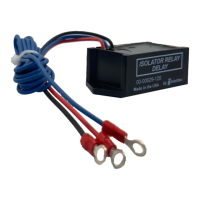
The Isolator Relay Delay/E is designed for straightforward integration into a vehicle's electrical system. It is fully encapsulated in a durable plastic enclosure, making it suitable for mounting in the engine compartment where it is protected from environmental elements. Installation typically involves connecting three wires from the delay unit: one to an ignition-switched 12-volt source, one to ground, and one to the coil of the isolator relay. This simple wiring scheme facilitates easy setup and minimizes complexity.
The device works in conjunction with a conventional continuous duty cycle isolator relay, a type of relay commonly used by various vehicle manufacturers. This compatibility ensures that the Isolator Relay Delay/E can be easily integrated into existing multi-battery setups or new installations without requiring specialized or proprietary relays. The unit's ability to manage the charging process automatically, based on voltage sensing, eliminates the need for manual intervention, providing a "set it and forget it" solution for battery management.
The delay mechanism for connecting the auxiliary battery is a crucial usage feature. By allowing the engine to warm up and the main battery to receive an initial charge, it optimizes the charging process and extends the life of both the alternator and the batteries. The automatic disconnection of the auxiliary battery during low voltage conditions safeguards the engine's operation, preventing potential stalls or power loss due to an overloaded charging system. The visual cue of flickering lights during an overload condition provides immediate feedback to the driver, allowing them to address the issue promptly.
The Isolator Relay Delay/E is designed for reliability and minimal maintenance. Its fully encapsulated construction protects the internal electronics from moisture, dust, and vibrations commonly found in engine compartments, contributing to its long-term durability. However, like any electrical component, occasional troubleshooting may be necessary.
The service manual provides clear guidance for diagnosing common issues. For instance, if the coach battery is not charging, the first step is to check if the chassis voltage (measured at the blue wire) is above 13.3 volts with the engine running. If the voltage is lower, it indicates a problem with the vehicle's charging system, not necessarily the Isolator Relay Delay/E itself. Checking the ground connection (black wire) on the module is another fundamental troubleshooting step.
To verify the functionality of the Isolator Relay Delay/E, one can check for voltage on the coil of the isolator relay (red wire) after the engine has been running for at least 20 seconds. If approximately 12 volts are present, the delay unit is likely functioning correctly. If no voltage is detected, it suggests a potential issue with the IRD/E unit itself, indicating a need for replacement.
If the chassis battery continues to drain, troubleshooting involves checking the voltage on the module with the ignition off. Both the red and blue wires should show 0 volts. If not, a wiring issue might be present. Additionally, checking for continuity across the isolator relay contacts with no voltage applied to the coil should show an open circuit. If the relay contacts are closed, the relay itself may be faulty and require replacement.
The service manual emphasizes that all servicing of this module should be performed by a qualified service technician. This recommendation highlights the importance of proper electrical knowledge to avoid damage to the unit or potential injury. Tools required for servicing include a low current test light and an accurate voltmeter (preferably digital read-out) to ensure precise measurements during diagnosis. The manual also includes a caution regarding the power fed into the module from both chassis and coach batteries, stressing that inadvertent shorts could lead to damage or injury, reinforcing the need for professional handling.
| Category | Relays |
|---|---|
| Voltage | 12V DC |
| Voltage Rating | 12 VDC |
| Operating Temperature Range | -40°C to 85°C |
| Contact Form | SPST (Single Pole Single Throw) |