Do you have a question about the Inter-m PAM-480A and is the answer not in the manual?
This section details crucial safety precautions, including warnings against electric shock and moisture exposure.
Guidance on selecting an appropriate operating environment to prevent performance degradation or reduced service life.
Comprehensive list of safety instructions to follow before, during, and after installation and operation.
Describes the system's flexibility with optional modules like CD players, tuners, or cassette decks.
Details rear-panel gain controls for precise adjustment of individual input channel levels.
Explains the six speaker select switches for flexible output configuration to up to five speakers.
Information on switchable audio signal priority for specific inputs over others.
Covers the remote control input for zone selection and chime operation on specific models.
Description of the built-in four-tone chime for announcements.
Details the optional emergency voice IC for EM broadcasting during emergencies.
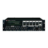
Panel designated for the installation of the optional PAM-T AM/FM Tuner module.
Bay for installing optional PAM-CDA (CD Player) or PAM-D (Cassette Deck) modules.
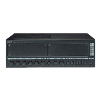
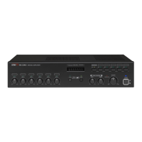
Seven-segment LED meter indicating the amplifier's real-time RMS output level.
Controls for adjusting the individual volume levels of Channels 1 through 6.
Bass and Treble controls for adjusting the amplifier's audio frequency response.
Rotary switch for controlling the overall output volume of the amplifier.
Button to activate the amplifier's built-in four-tone chime circuitry.
Switches used to select output to specific combinations of up to five individual speakers.
Main switch to turn the amplifier unit on or off.
LED indicating the status of the amplifier's protection circuitry, signaling normal or abnormal operation.
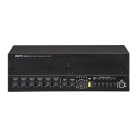
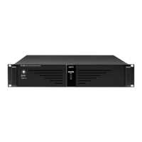
Terminal strip for connecting up to five individual speakers to the amplifier.
Switch to select between high-impedance (70V/100V) and low-impedance (4Ω) operation.
Terminal for connecting an antenna when using the optional PAM-T AM/FM Tuner module.
Three-band equalization controls for adjusting high, mid, and low frequencies of input signals.
Switch to enable/disable +22V DC phantom power for microphone inputs.
Switches to grant priority to Channels 1 and/or 2 over other audio inputs.
Standard connection point for the unit's AC power cable.
Terminals to activate the four-tone chime circuitry via an external source.
Terminals to mute specific input channels via a wired remote control.
Terminals for connecting a 24VDC battery source for backup power.
Output for connecting to an external power amplifier.
Input for connecting an external mixer or preamp to the unit's power amp.
Line-level input for connecting an external mixer to expand input channels.
Balanced XLR connectors for microphone or other low impedance signal inputs.
Knobs for continuous adjustment of input levels for each of the six input channels.
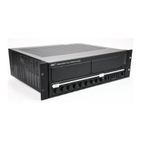
Terminal strip for connecting up to five individual speakers to the amplifier.
Terminal for connecting an antenna when using the optional PAM-T AM/FM Tuner module.
Three-band equalization controls for adjusting high, mid, and low frequencies of input signals.
Switch to enable/disable +22V DC phantom power for microphone inputs.
Switches to grant priority to Channels 1 and/or 2 over other audio inputs.
Standard connection point for the unit's AC power cable.
Function to output EM broadcasting stored in VOICE IC during emergencies.
Terminals to activate the four-tone chime circuitry via a wired remote.
Terminals to mute specific input channels via a wired remote control.
15-pin D-SUB connector for controlling speaker zones and chime via remote.
Output for connecting to an external power amplifier.
Input for connecting an external mixer or preamp to the unit's power amp.
Line-level input for connecting an external mixer to expand input channels.
Balanced XLR connectors for microphone or other low impedance signal inputs.
Knobs for continuous adjustment of input levels for each of the six input channels.
Instructions for connecting conventional low-impedance speaker systems to the amplifier.
Guidance on connecting high-impedance distributed speaker systems in parallel.
Diagram illustrating typical input and output connections for the PAM-120A amplifier.
Diagram illustrating typical input and output connections for the PAM-340A/480A amplifiers.
Internal schematic showing the signal flow and component layout for the PAM-120A.
Internal schematic showing the signal flow and component layout for the PAM-340A/480A.
Steps to ensure problems are not operator error and how to contact warranty provider.
Information on how to obtain a service schematic for the unit.
Information on how to obtain a parts list for the unit.
Details on product compatibility with local AC power requirements.
Statement indicating that no optional items are available for this product.
| Type | Power Amplifier |
|---|---|
| Output Power | 480W |
| Channels | 2 |
| Total Harmonic Distortion (THD) | < 0.1% |
| Signal-to-Noise Ratio | > 100dB |
| Cooling | Fan |
| Frequency Response | 20Hz - 20kHz (±0.5dB) |
| Input Impedance | 20kΩ |
| Output Impedance | 4Ω / 8Ω |
| Power Source | AC 220V~240V 50/60Hz |