Interklima Dx Cassette Units
II-IO CCV1 R410A / Rotary / Scroll
49
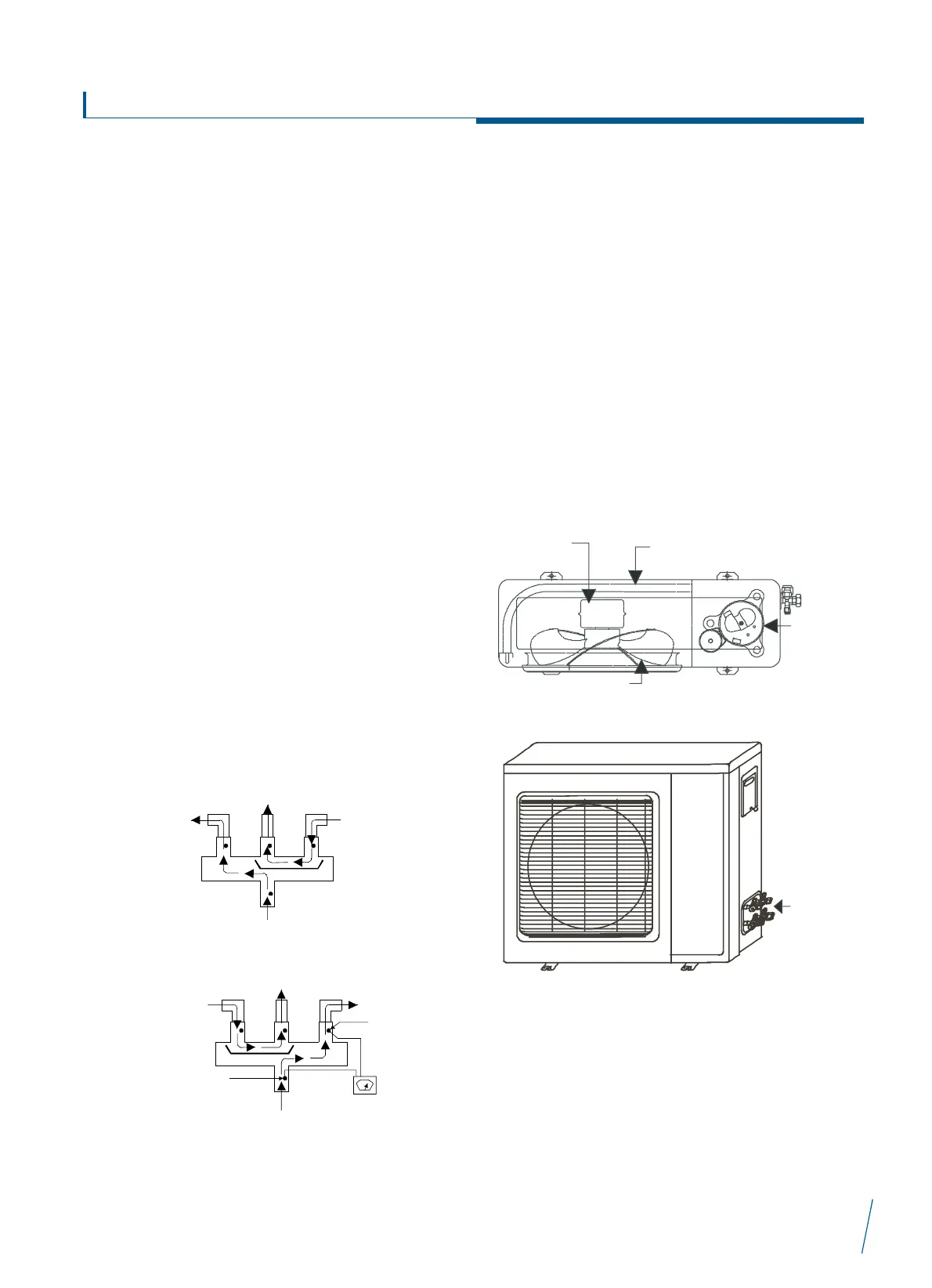
SERVICE (PACK) VALVES- The service valves in the condensing
unit come from the factory closed. This means the refrigerant
charge is isolated from the line side of the connection ports. The
service valves must be opened (turned counter clockwise until
seated) before the service port caps can be removed and the
hoses of the gauge manifold connected. in this position, the
refrigerant has access from and through the outdoor and indoor
unit. The service valves can not be field repaired.
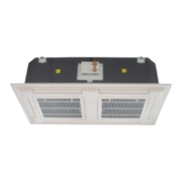
REVERSING VALVE- In heat pumps, the change over between
heating and cooling modes is accomplished with a valve that
reverses the flow of refrigerant in the system. The reversing valve
solenoid can be checked when the power is off with an ohm meter.
Check for continuity and shorting to ground. With the control circuit
(230V) power on, check for the correct voltage at the solenoid coil.
Check for a burned or overheated solenoid. With the unit operating,
other items can be checked, such as frost or condensate water on
the refrigerant lines. Using a remote measuring device, check the
inlet and outlet line temperatures. Do not touch the lines. if the
reversing valve is operating normally, the inlet and outlet
temperatures on the appropriate lines should be close. Any
difference would be due to heat loss or gain across the valve body.
Temperatures are best checked with a remote reading electronic
type thermometer with multiple probes. Figures 3 and 4 show test
points (tp) on the reversing valve for recording temperatures.
Insulate points for a more accurate reading. If the valve is defective;
shut off all power to the unit and remove all charge from the system.
Remove the valve using a tubing cutter. Wrap the new valve with a
wet rag to prevent over heating while brazing.
After the valve is brazed in, check for leaks, evacuate and charge
system. Operate the system in both heat and cool modes several
times to be sure the valve functions properly.
CLEANING COILS - The coil should be washed out with water, or
blown out with compressed air. Clean the coil annually, or as
required by the location or outdoor air conditions. Inspect the coil
monthly and clean as required. Dirt and debris may pass through
the first coil section, then become trapped between the rows of
fins and restrict the condenser air flow. Use a flashlight to
determine if any dirt or debris has collected between the coil
sections. Clean coil as follows:
1. Turn off unit power.
2. Using a water hose, or any other suitable equipment, flush
the coil from the outside to remove dirt. Be sure to flush all
dirt and debris from the drain holes in the base of the unit.
 Loading...