Do you have a question about the Interklima II09CCV1 and is the answer not in the manual?
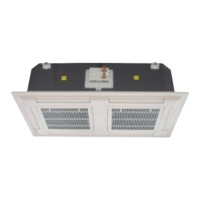
Detailed description of the Interklima Ceiling Mounted 4-Way Blow Cassette Cooling/Heating Terminal Unit.
Highlights of the unit's capabilities including optimized design, stylish appearance, and quiet operation.
Explanation of the coding system used for Interklima cassette units, detailing each component of the model number.
Table detailing nominal cooling and heating capacities, EER, and COP for various models.
Information on power supply, input power, running current, and start current for different unit configurations.
Specifications for indoor and outdoor unit dimensions, panel dimensions, and net weights.
Details on noise levels at 1m distance and airflow rates (H/M/L) for indoor units.
Detailed diagrams showing dimensions and connection points for the indoor cassette unit models.
Diagrams illustrating the dimensions and external views of the outdoor unit models.
Diagram illustrating the refrigerant flow path for cooling and heating cycles within the system.
Detailed electrical wiring diagrams for the indoor unit, including component legends.
Electrical wiring diagrams for the outdoor unit, showing compressor, fan motor, and valve connections.
List of accessories included with the unit for installation and operation.
Guidelines for choosing an appropriate installation location and preparing the site.
Instructions on how to mount the cassette unit, including suspension bolt details and ceiling types.
Details on connecting branch ducts, fresh air ducts, and drain pipes.
Procedures for installing fresh air intake and branch ductwork for optimal air distribution.
Instructions for applying blanking plates to cover openings in the supply air tunnel.
Information on compressor lubricant types and procedures for charging the system with R-410A refrigerant.
Steps for unpacking, inspecting, and mounting the condensing unit, including rigging procedures.
Guidelines for making refrigerant piping flare connections and completing electrical wiring.
Procedure for safely starting the unit and initial operational checks.
Detailed steps for performing leak tests, evacuation, and pumping down the system.
Explanation of the remote controller's buttons, display, and basic functions like mode and fan speed selection.
Description of the wired wall pad's functions, including temperature setting, timer controls, and error display.
Overview of system control, power-on settings, compressor delay, and available modes like Auto, Cool, Heat.
Detailed operational logic for the cool mode, including temperature settings and fan speed adjustments.
Detailed operational logic for the heat mode, including temperature settings and fan speed adjustments.
Explanation of safety features like over-heat protection, refrigerant shortage, and pressure protection.
Description of Sleep Mode, Ventilation Mode, Dehumidification Mode, and Auto Heat-Dehumidification-Cool Mode.
Details on louver movement, buzzer feedback, auto-restart function, and reset button operation.
Explanation of how the drain pump operates in different modes and conditions.
Essential safety steps and general maintenance advice before performing any service.
Procedure for accessing, removing, cleaning, and reinstalling the air filter.
Diagrams showing unit assembly and procedures for removing the fan blower and drain pan.
Instructions for handling service valves, reversing valves, and cleaning the condenser coils.
Tables and notes for charging refrigerant based on model and piping length.
Data showing how increased piping length affects unit capacity.
Table specifying the maximum and minimum operating temperatures for indoor and outdoor units.
Table listing error codes, their failure sources, and recommended actions.
Explanation of LED light indicators for normal operation and various malfunction states.
| Brand | Interklima |
|---|---|
| Model | II09CCV1 |
| Category | Computer Hardware |
| Language | English |