Interklima Dx Cassette Units
II-IO CCV1 R410A / Rotary / Scroll
36
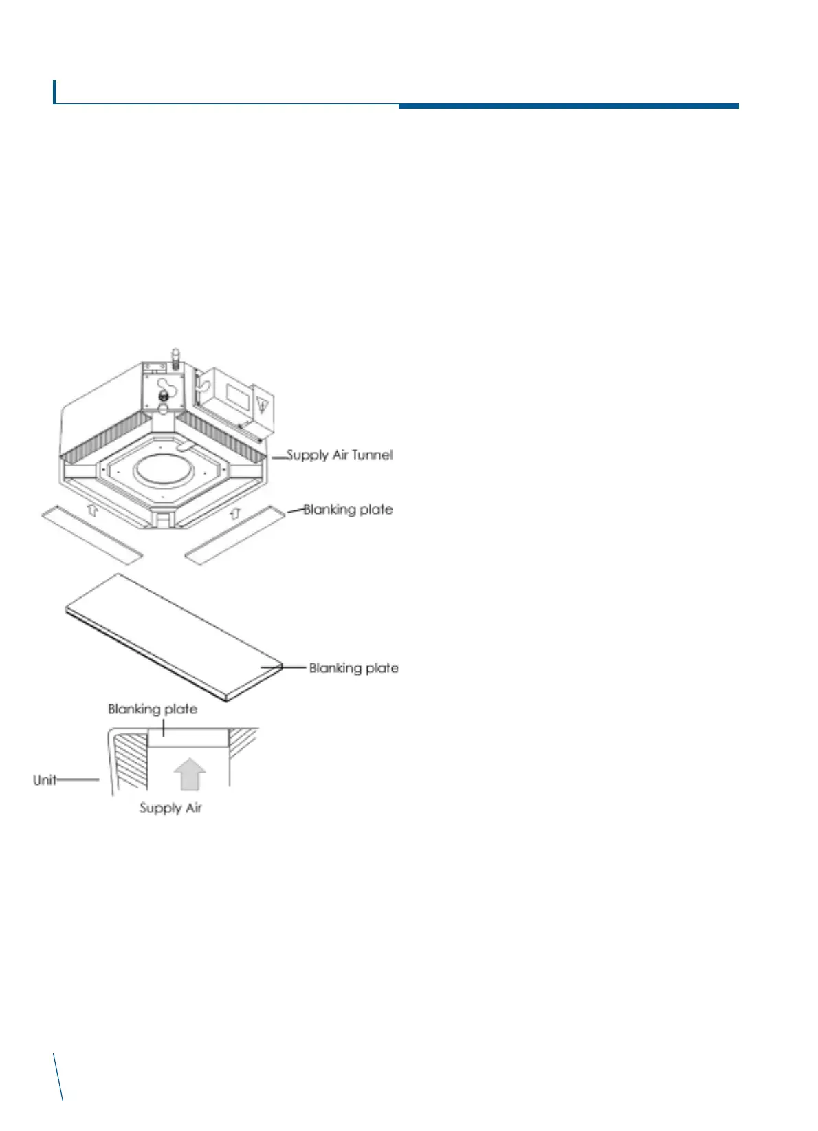
BLANKING PLATES
See the following diagram and installation method.
How to install
1) Peel off the cover paper to expose adhesive surface of the
blanking plate.
2) Apply blanking plate on the supply air tunnel to cover the
opening.
3) Press on the attaching area to firmly seal it.
INSTALLATION, START UP AND SERVICE INSTRUCTIONS FOR
CONDENSING UNITS
COMPRESSOR LUBRICANT: POE(polyol ester) or synoil are
typically used as the lubricant for R-410A.
CHARGING SYSTEM WITH R-410A: It is essential when charging
the system with R-410A that the system be liquid charged by
removing only liquid from the cylinder. Never charge the system
with vapour from a cylinder. Vapor charging R-410A may result in
the wrong refrigerant composition and could damage the system.
Therefore the cylinder must be equipped with a dip tube to
facilitate liquid removal with the cylinder in the upright position.
LEAK DETECTION: Service personnel have used leak detection
equipment for years when servicing equipment. Leak detectors exist
not only for pinpointing specific leaks, but also for monitoring an
entire room on a continual basis for the absence of oxygen or
presence of r frigerants. There are several reasons for leak
pinpointing or area monitoring, including: conservation of
refrigerants, protection of valuable equipment, reduction of fugitive
emissions, and protection of employees. Prior to the purchase of
detector or monitor, make sure you consider your requirements or
criteria for the monitor such as sensitivity, detection limits, and
selectivity. Another simple method used to find leaks is to coat the
suspect area with a soapy water solution and look for soap bubbles.
CHECK SYSTEM OPERATION: Start the system and let conditions
stabilize. If the system is under charged, add additional R-410A in
increments of 5 percent by weight. Continue until desired
conditions, 2700 kpa for high pressure and 700 kpa for low
pressure, are achieved.
REFRIGERANT CHARGING: If recharging is necessary, weight in
the total charge as indicated in the charging table. Remove any
refrigerant remaining in the system before recharging. If the system
has lost the complete charge, evacuate and recharge by weight.
STEP 1 - COMPLETE PRE-INSTALLATION CHECKS
UNPACK UNIT - Move unit to its final location. Remove the carton
from unit being careful not to damage the service valves and grilles.
INSPECT SHIPMENT - File a claim with the shipping company if
the shipment is damaged or incomplete.
CONSIDER SYSTEM REQUIREMENTS - Consult the local building
and national electrical codes for any special installation
requirements.
Allow sufficient space for air flow clearance, wiring, refrigerant
piping, and servicing the unit. See fig. 1.Locate the unit so that the
condenser's air flow is unrestricted on both sides. Refer to fig. 2.
The unit may be mounted on a level pad directly on its base legs
or mounted on raised pads at the support points.
STEP 2 - RIG AND MOUNT UNIT
MOUNTING ON GROUND - Mount on a solid, level, concrete pad.
Position unit so water or ice from the roof cannot drop directly
onto the unit. If local codes require the unit be fastened to the pad,
tie down bolts should be used and fastened through the slots
provided in the unit's mounting feet.
MOUNTING ON ROOF - Mount on a level platform or frame. See fig.2.
RIGGING
Be sure unit panels are securely in place prior to rigging.
Keep unit upright. Lift unit using slings. Use cardboard or padding
 Loading...