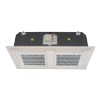
Interklima Dx Cassette Units
II-IO CCV1 R410A / Rotary / Scroll
37
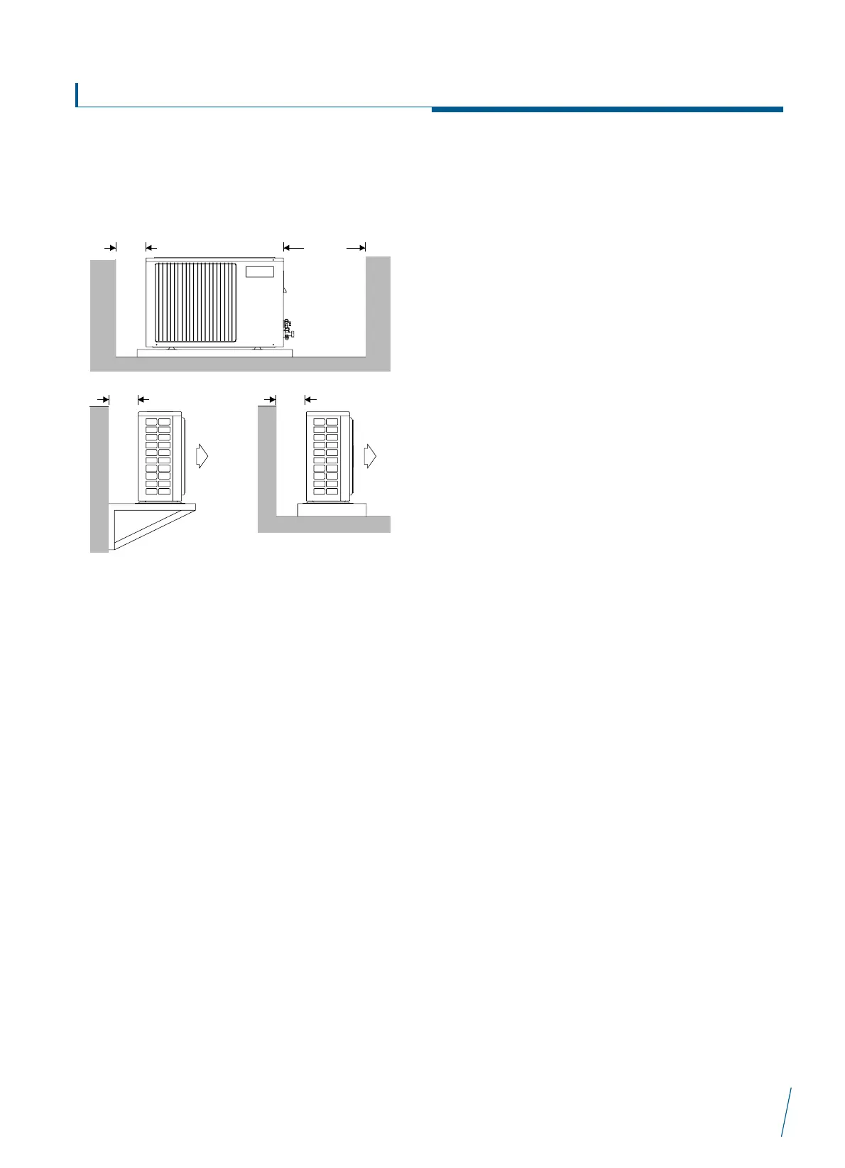
under sling, and spreader bars to prevent any sling damage to the
unit. Install the unit so that the coil does not face into prevailing
winds. If this cannot be done, and constant winds above 22
kM/HR are expected, use a wind baffle.
STEP 3 - COMPLETE REFRIGERANT PIPING CONNECTIONS
The condensing units may be connected to the evaporator section
using field supplied tubing of the correct refrigerant grade, size
and condition. Do not use less than 3m of interconnecting tubing
and do not bury more than one metre of line set underground.
If more than the recommended length is buried, the refrigerant
may migrate to the cooler buried section during extended periods
of unit shutdown. This causes refrigerant slugging and possible
compressor damage at start-up.
When more than 15 m of inter-connecting tubing and /or more
than 10 m vertical lift is used, consider the amount of liquid lift and
compressor oil return or contact your local distributor.
If either the refrigerant tubing or indoor coil is exposed to
atmospheric conditions for longer than 1 minute, it must be
evacuated to 1,000 microns to eliminate contamination and
moisture in the system. Run the refrigerant tubes as directly as
possible, avoiding unnecessary turns and bends. Suspend the
refrigerant tubes so they do not damage
Insulation on the vapour tube and do not transmit vibration to the
structure. Also, when passing the refrigerant tubes through the
wall, seal the opening so vibration is not transmitted to the
structure. Leave some slack in the refrigerant tubes between the
structure and unit to absorb vibration. Refer to evaporator
installation instructions for additional information.
MAKING PIPING FLARE CONNECTIONS
Both the suction and liquid lines of the units are equipped with
flare connections which are closed off in the factory and ready for
connection. Use refrigerant grade tubing. Assemble flared joint by
aligning the tubing with the machined surface of the fitting. Turn
the nut anti-clockwise and then clockwise until it is fully tightened.
Leak test the joint to ensure it is leak free.
STEP 4 - COMPLETE ELECTRICAL CONNECTIONS
POWER WIRING - The unit is factory wired for the voltage shown
on the name plate. Provide an adequate fused disconnect switch
within sight of the unit, readily accessible, but out of reach of
children. Provision for locking the switch open (off) is advisable to
prevent power from being turned on while unit is being serviced.
Disconnect switch, fuses, and field wiring must comply with local
code requirements. Use only copper wire between the disconnect
switch and unit. Route power wires through the opening in unit’s
side panel and connect to the unit control box as shown on the
unit’s label wiring diagram. Unit must be grounded.
CONTROL CIRCUIT WIRING - The control voltage is 12 VDC. See
unit label wiring diagram. Route the control wires through the
opening in the unit’s side panel to connect into the unit control box.
STEP 5 - PRELIMINARY CHECKS
[1] Check that all internal connections are tight and that all
barriers, covers and panels are in place.
[2] The field electrical power source must agree with the unit
nameplate rating.
[3] All service valves must be open.
LEAK TEST SYSTEM and field piping by pressure method. At
approximately 170 kpa backed up with an inert gas to a total
pressure not to exceed 1600 kpa.
EVACUATION AND DEHYDRATION of the field piping and fan coil
is necessary. Service valves must be fully back-seated to close
the service port. There is no valve at the service port and failure to
back seat the valve could result in a loss of the system charge or
personal injury.
TO START UNIT - Ensure the main power is switched on by closing
the disconnect switch and the cooling temperature required is set
below room temperature. The unit compressor will start after a 3
minute delay. Operate the unit for 15 minutes, then check the
system refrigerant charge. See refrigerant charging table.
 Loading...