Interklima Terminal Units
PCE -VS ñ Hydronic cassette
8
Qw1/h
1544
1831
2128
1231
1456
1707
900
1057
1231
633
733
818
553
638
702
Pf kW
7.10
8.40
9.76
5.61
6.61
7.73
4.02
4.70
5.46
2.45
2.82
3.22
2.05
2.34
2.64
Pfs kW
5.19
5.90
6.67
4.63
5.24
5.91
3.92
4.60
5.17
2.37
2.76
3.14
2.01
2.29
2.57
Tad
10.7
11.4
12.1
12.2
12.9
13.5
14.1
14.3
14.9
18.3
18.5
18.8
19.3
19.6
19.9
Taw
10.4
10.5
10.7
12.1
12.2
12.3
13.8
13.9
14.0
15.4
15.5
15.6
15.8
15.9
16.0
Pf kW
7.94
9.41
10.93
6.31
7.40
8.75
4.58
5.38
6.25
3.17
3.68
4.23
2.76
3.19
3.65
Pfs kW
5.72
6.46
7.21
5.04
5.78
6.47
4.44
5.07
5.70
3.08
3.61
4.14
2.69
3.09
3.58
Tad
11.2
12.1
13.0
13.0
13.5
14.4
14.6
15.2
15.8
18.3
18.5
18.8
19.4
19.7
19.9
Taw
11.0
11.1
11.3
12.8
12.9
13.0
14.6
14.7
14.8
16.0
16.1
16.2
16.4
16.5
16.6
Pf kW
8.18
9.70
11.27
6.52
7.71
9.04
4.77
5.60
6.52
3.35
3.88
4.33
2.93
3.38
3.72
Pfs kW
5.57
6.28
7.05
4.92
5.60
6.30
4.29
4.93
5.50
3.27
3.78
4.20
2.84
3.31
3.63
Tad
11.6
12.5
13.3
13.3
14.0
14.7
15.0
15.5
16.2
17.8
18.1
18.7
19.0
19.2
19.8
Taw
11.4
11.5
11.7
13.2
13.3
13.4
15.0
15.1
15.2
16.4
16.5
16.7
16.8
16.9
17.1
Pf kW
9.35
11.09
12.93
7.55
8.94
10.5
5.65
6.65
7.78
3.86
4.50
5.20
3.30
3.82
4.23
Pfs kW
5.61
6.32
7.00
4.93
5.60
6.31
4.37
4.89
5.57
3.83
4.40
4.90
3.20
3.71
4.10
Tad
13.4
14.3
15.3
15.2
15.9
16.6
16.7
17.5
18.0
18.2
18.7
19.3
19.9
20.2
20.8
Taw
12.1
12.2
12.4
14.0
14.1
14.2
15.9
16.0
16.1
17.6
17.7
17.8
18.1
18.2
18.4
DpwkPa
12.9
17.5
23.0
8.6
11.6
15.4
4.9
6.5
8.6
2.6
3.37
4.1
2.03
2.63
3.1
Qa[m3/h]
1050
1262
1502
1051
1262
1504
1052
1262
1503
1058
1265
1510
1059
1267
1508
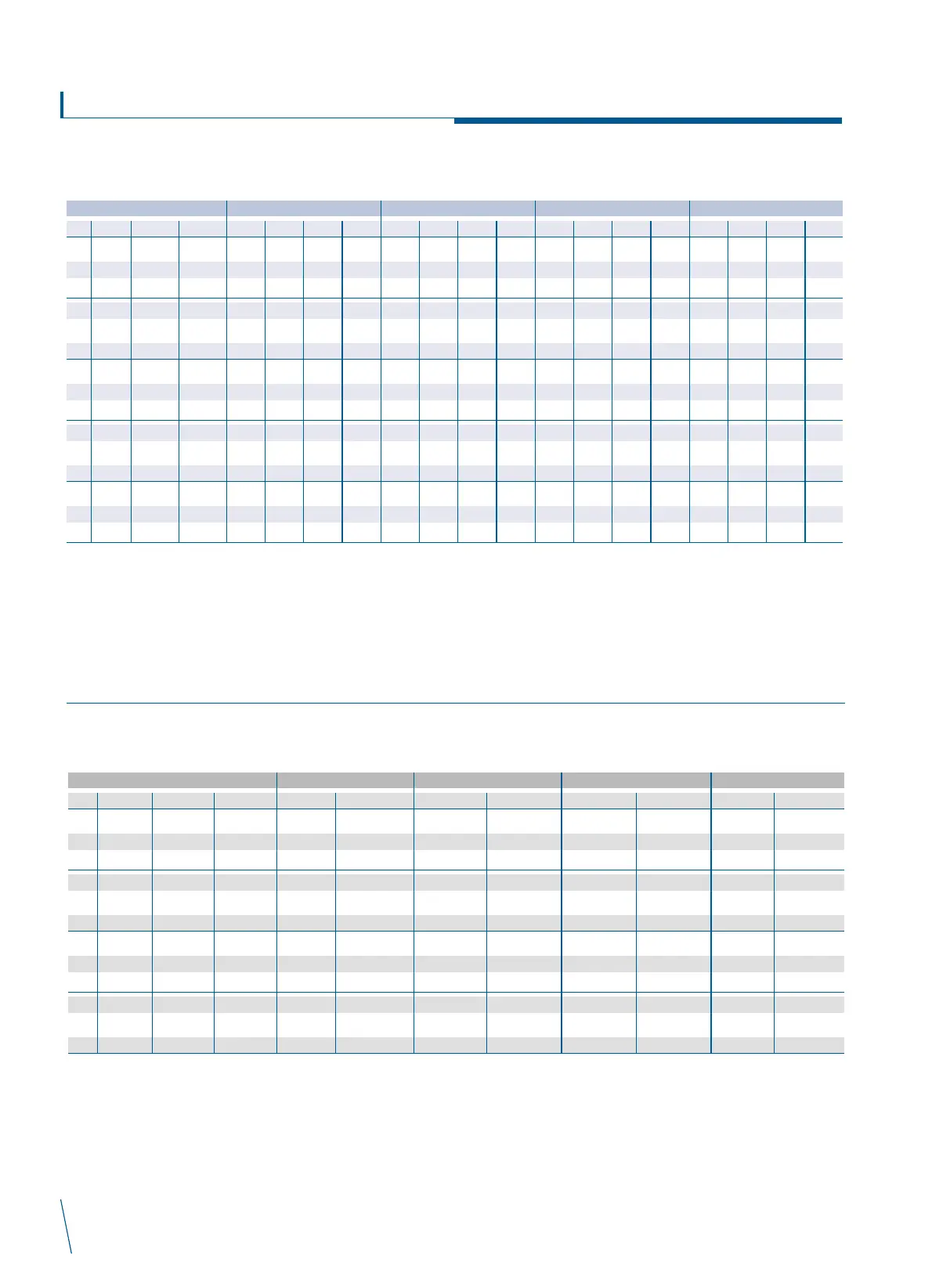
PCE-16
Twi
5
7
9
11
13
TAI DB25-WB17.8 TAI DB27-WB19 TAI DB27-WB19.5 TAI DB29-WB21.1
PCE-16
NOTES
TAI: Air in temperature Pf: Total cooling capacity
TWI: Fluid in temperature Pfs: Sensible cooling capacity
Qw: Fluid flow rate in heat exchanger tad: Discharge air dry bulb temperature
Dpw: Pressure drop standard coil Taw: Discharge air wet bulb temperature
Qa: Air flow
Design and specification are subject to change without prior notice for product improvement
Qw 1/h
105
122
133
183
211
236
267
314
346
351
413
449
Pf kW
1.46
1.72
1.87
2.51
2.96
3.26
3.58
4.24
4.66
4.65
5.51
6.00
Tad
32.0
31.4
30.6
42.0
41.0
40.0
52.1
51.0
49.5
62.3
61.0
58.5
Pf kW
1.35
1.56
1.71
2.35
2.71
3.03
3.42
4.03
4.44
4.50
5.31
5.76
Tad
32.9
32.2
31.5
42.5
41.2
40.4
52.6
51.5
50.0
62.7
61.6
58.8
Pf kW
1.20
1.40
1.53
2.23
2.58
2.85
3.28
3.81
4.26
4.31
5.10
5.59
Tad
33.5
33.0
32.3
43.3
42.2
41.2
53.4
51.7
50.8
63.4
61.5
59.7
Pf kW
1.06
1.24
1.37
2.07
2.40
2.67
3.11
3.64
4.05
4.15
4.88
5.35
Tad
34.2
33.7
33.2
43.8
42.7
42.0
53.9
52.3
51.3
63.9
62.0
60.2
DpwkPa
0.410
0.530
0.627
1.110
1.440
1.760
2.180
2.930
3.500
3.580
4.800
5.580
Qa[m3/h]
323
395
459
323
395
459
324
395
458
326
394
458
PCE-03
Twi
40
50
60
70
TAI 18 TAI 20 TAI 22 TAI 24
Heating
PCE-03
NOTES
TAI: Air in temperature Pf: Total cooling capacity
TWI: Fluid in temperature tad: Discharge air dry bulb temperature
Qw: Fluid flow rate in heat exchanger
Dpw: Pressure drop standard coil
Qa: Air flow
Design and specification are subject to change without prior notice for product improvement
 Loading...