EasyManua.ls Logo

Interlogix 511C User Manual

Interlogix 511C
6 pages
To Next Page IconTo Next Page
Page #1 background imageLoading...
Page #1 background image
1
ESL 500 Series
ESL 500 Series
Smoke Detector
Installation Instructions
Description
The ESL 500 Series Smoke Detectors offer 2-wire, 4-wire, 12VDC,
and 24VDC detectors for fire system applications.
Depending on the model, the smoke detector provides the following
features:
Detector/base lock
Discourages unauthorized removal of the smoke detector by requiring
a screwdriver to remove the detector from the base.
CleanMe®
Enables the control panel to receive a warning signal via a 505
module, or CleanMe compatible panel, indicating that the optical
chamber needs to be replaced. This feature is available on the 521/
528 Series 2-wire detectors only.
The detectors ship with the CleanMe feature turned off. To turn on
the CleanMe signal move DIP switch 2 on the back of the detector to
the “on” position. See Figure 1.
Self-diagnostics
Includes automatic sensitivity testing. Once a day and immediately
upon first power up, each 500 Series detector performs a full
diagnostic test that includes a dynamic test of the sensing chamber
and internal electronics. This meets NFPA 72 field sensitivity testing
requirements without the need for external meters.
Drift compensation
The detectors automatically adjust sensitivity, up to a maximum of
1.0%/ft., as the detectors become dirty.
Using the 2-wire 521/528 Series with a panel that does not have 2-
wire capabilities
The ESL 505 module can convert the 2-wire 521/528 Series to a 4-
wire input on the control panel. The 521/528 Series is UL Listed as
compatible with the 505 module and will be fully UL compliant with
any UL listed 24 VDC control panel and panels that do not operate
below 12V. Each 505 module will accommodate up to 20 ESL 521/
528 Series smoke detectors. See the 505 module installation
instructions for more information.
Selectable voltage range for UL 2-wire compatibility
The 500 Series 2-wire smoke detectors have a DIP switch that allows
the installer to choose between 12/24V operation and 6/12V
operation. See Figure 1 and Specifications.
Note
Please refer to the ESL Compatibility Index for a complete
listing of control panels and proper identifiers. For a copy
of the Compatibility Index, call 1-800-648-7424 or visit
www.sentrol.com for a copy to down load. Remember,
4-wire smoke detectors do not require a
compatibility listing.
WARNING
This document is intended for licensed electricians/
alarm installers. Interlogix cannot provide technical
support to unqualified persons.
If you have questions, call Interlogix at 1-800-648-7424.
Selecting a Location
Selecting a suitable location is critical to the operation of smoke
detectors. This equipment should be installed in accordance with
the National Fire Protection Association’s (NFPA) Standard 72.
A-8-1.2.1.a Where to Locate the Required Smoke Detectors in
Existing Construction. The major threat from fire in a family
living unit occurs at night when everyone is asleep. The
principal threat to persons in sleeping areas comes from fires in
the remainder of the unit. Therefore, a smoke detector(s) is best
located between the bedroom areas and the rest of the unit. In
units with only one bedroom area on one floor, the smoke
detector(s) should be located as shown in Figure 2 A.
In family living units with more than one bedroom area or with
bedrooms on more than one floor, more than one smoke detector
is required, as shown in Figure 2 B.
Figure 2. Detector placement
2 A
= Required smoke detectors
= Additional smoke detectors required for new construction
Dining
Room
Kitchen
Bedroom
Bedroom
Bedroom
Living Room
TV Room
Dining
Room
Kitchen Bedroom
Bedroom
Bedroom
Living Room
Dining
Room
Basement
Bedroom
Bedroom
Living
Room
2 B
2 C
Figure 1. Switches
12
ON
1. On=A (6-12V) range
Off=C (12-24V) range
2. On=CleanMe signal on
Off=CleanMe signal off
(521/528 Series only)
Note
Turning the CleanMe signal
on without using the 505
module and/or compatible
panel will create a trouble
signal.
NO COM NC
Relay (CRXT) unit only
Correct Incorrect
X
ON
1 2
Question and Answer IconNeed help?

Do you have a question about the Interlogix 511C and is the answer not in the manual?

Interlogix 511C Specifications

General IconGeneral
Power Source120VAC with 9V Battery Backup
TypePhotoelectric
Operating Voltage120VAC
Operating Temperature40°F to 100°F
Operating Humidity10% to 95% relative humidity (non-condensing)
Alarm Sound Level85dB at 10 feet
Interconnect CapabilityUp to 12 units
Hush FeatureYes
LED IndicatorYes
ComplianceUL 217

Summary

ESL 500 Series Smoke Detector Description

Detector Base Lock Mechanism

Discourages unauthorized removal using a screwdriver to detach the detector from its base.

CleanMe Feature for Optical Chamber

Notifies the control panel when the optical chamber needs replacement, available on 521/528 Series.

Automatic Self-Diagnostics

Performs daily and on-power-up diagnostic tests, meeting NFPA 72 field sensitivity testing needs.

Drift Compensation for Sensitivity

Automatically adjusts sensitivity up to 1.0%/ft to compensate for detector dirt accumulation.

2-Wire 521/528 Series Panel Compatibility

Uses ESL 505 module to convert 2-wire detectors to a 4-wire input for panels without 2-wire capability.

Selectable Voltage Range for 2-Wire

DIP switch allows installer to select between 12/24V or 6/12V operation for 2-wire models.

Selecting Smoke Detector Location

Detector Placement in Existing Construction

Locate between sleeping areas and the rest of the unit for optimal early warning against fire threats.

Detector Placement in New Construction

Requires detectors as in existing construction, plus an additional detector in each bedroom.

Recommended Additional Detector Locations

Suggests extra detectors for areas not covered by code for increased protection and early warning.

General Location Guidelines

Avoid bathrooms, kitchens, and ventilation sources; maintain distance from walls and ceilings.

Detector Installation Procedure

Detector/Base Lock Preparation

Remove knockout and break tab on mounting base if utilizing the detector/base lock feature.

Wiring and Mounting

Run system wiring to location, mount electrical boxes, attach gasket and base, and connect wires.

Attaching Detector to Base

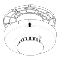
Align the raised tab on the detector with the arrow on the base, insert, and turn clockwise 15 degrees.

Smoke Testing and Detector Sensitivity

Sensitivity Testing Procedure

Use a test magnet on the detector's TEST letters and observe LED flashes to determine sensitivity.

Interpreting Sensitivity Test Results

Table details flash counts for unserviceable faults, low sensitivity, normal range, and high sensitivity.

Detector Cleaning Process

Clean exterior with damp cloth; replace optical chamber by removing cap, discarding old chamber, and installing new.

Detector Maintenance and Safety

Routine Detector Maintenance

Detectors require minimal maintenance and should be tested monthly for proper function.

Fire Prevention and Escape Planning

Emphasizes avoiding fire hazards and preparing an escape plan, including drills and meeting points.

Limitations of Smoke Detectors

Highlights that detectors are not substitutes for life insurance and have limitations in detecting all fires.

Product Specifications and Ordering

ESL 500 Series Specifications

Details electrical ratings, operating conditions, sensitivity, dimensions, and certifications for various models.

ESL 500 Series Product Models

Lists available models by part number, description (e.g., 2-wire, 4-wire, heat sensor), and voltage.

Available Accessories

Lists compatible accessories such as CleanMe modules, test magnets, canned smoke, and replacement chambers.