Do you have a question about the Interlogix ATS1110A and is the answer not in the manual?
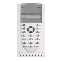
Details on the rear tamper switch and its function for system operation.
Configuration of RAS address and bus termination using DIP switches.
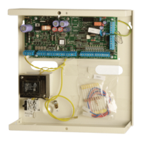
Mandatory data cable shield connection requirements for NF & A2P compliance.
Troubleshooting steps for common issues like no LED/LCD display or system faults.
Configures the request to exit (RTE) control port for door release.
Selects reader recognition mode: Unsecured or Secured card types.
Selects data transmission method: Wiegand, Magnetic Stripe, or Tecom Smart Card.
| Model | ATS1110A |
|---|---|
| Manufacturer | Interlogix |
| Users | Up to 50 |
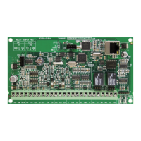
| Zones | 8 |
| Power Supply | 16.5VAC |
| Operating Temperature | 0°C to 49°C |
| Humidity | 95% non-condensing |
| Compatibility | ATS panels |