© 2019 United Technologies Corporation. P/N 1073550-EN • REV B • ISS 01FEB19
Interlogix is part of UTC Climate, Controls & Security, a unit of United Technologies Corporation. All rights reserved. All trademarks are the property
of their respective owners. Information in this document is subject to change without notice.
NS3552-8P-2S-V2 Quick Installation Guide
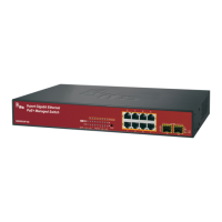
Figure 1: NS3552-8P-2S-V2 Industrial L2+ Multi-Port Managed
Ethernet Switch
Package contents
Thank you for purchasing the IFS NS3552-8P-2S-V2 L2+
industrial managed switch. The description of this model is as
follows:
-8P-2S-V2
Industrial 8-Port 10/100/1000T 802.3af/at PoE+
+ 2-Port 100/1000X SFP Managed Switch
Unless specified, the term “industrial managed switch”
mentioned in this quick installation guide refers to the above
model.
Open the box of the industrial managed switch and carefully
unpack it. The box should contain the following items:
The industrial managed switch × 1
Quick installation guide × 1
DIN rail kit × 1
Wall mounting kit × 1
DB9 to RJ45 interface RS-232 console cable × 1
Dust cap × 11
If any of these are missing or damaged, contact your dealer
immediately. If possible, retain the carton including the original
packing materials for repacking the product in case there is a
need to return it to us for repair.
Requirements
The industrial managed switch provides a remote login
interface for management purposes. The following equipment
is necessary for further management:
Workstations running Windows
®
XP / 2003 / Vista / 7 / 8 /
2008 / 10, MAC OS X or later, Linux, UNIX, or other
platforms are compatible with TCP/IP protocols.
Workstations are installed with Ethernet NIC (Network
Interface Card)
Serial port connection (Terminal)
The above workstations come with a COM Port (DB9)
or USB-to-RS-232 converter.
The above workstations have been installed with a
terminal emulator, such as Hyper Terminal included in
Windows XP/2003.
Serial cable – One end is attached to the RS-232
serial port, and the other end is attached to the
console port of the managed switch.
Ethernet port connection
Network cables – Use standard network (UTP) cables
with RJ45 connectors.
The above workstations have a web browser and
JAVA runtime environment plug-in installed.
Caution: When installing the industrial managed switch,
ensure a clearance of two inches at the top and bottom of the
device to allow for proper cooling.
Note: We recommend using Internet Explorer 11.0 or later to
access the industrial managed switch. If the web interface of
the switch is not accessible, turn off the anti-virus software or
firewall and then try it again.
Wiring the power inputs
The upper panel of the industrial managed switch indicates a
DC inlet power socket and consists of one terminal block
connector within six contacts. Follow the steps below to insert
the power wire:
1. Insert the positive/negative DC power wires into contacts 1
and 2 for Power 1, or contacts 5 and 6 for Power 2.
NS3552-8P-2S-V2: DC 12~48 V