EasyManua.ls Logo

Intermatic EI400WC - User Manual

Intermatic EI400WC
2 pages
Print Icon
To Next Page IconTo Next Page
Loading...
If a Single Switch Setup:
Connect one of the two wires from a.
the wall to the black wire from the
timer, using the twist connectors
provided.
Connect the other wire from the
b.
wall to the blue wire from the
timer, using the twist connectors
provided.
NOTE: The RED wire is not used
in single-switch installations. Cap with a twist connector.
Connect the GREEN wire to the grounding screw in the box. If a c.
plastic box, connect to ground as supplied.
Make sure all twist connectors are tight.d.
If a 3-Way Switch Setup:
NOTE: The distance between
timer and remote switch must not
exceed 100 feet.
Locate the COMMON wire a.
connected to first old switch.
It might be attached to a dif-
ferent colored screw, or find markings on old switch.
Connect BLACK wire from timer to COMMON wire, using a twist b.
connector.
Connect the other two wires from the old switch as follows: one c.
to the BLUE wire and the other to the RED wire from the timer.
Connect the GREEN wire to the grounding screw in the box. If a d.
plastic box, connect to ground as supplied.
Using diagram #1 below. Identify and remove wire “C” from the e.
“Common” terminal of your existing remote switch.
Using diagram # 2 below, remove and reconnect wires “B” and f.
“C” to the “Common” terminal of your remote switch, using a
jumper wire, if necessary. Follow diagram # 3 below, if using a
new single-pole remote switch.
NOTE: For new construction or to replace a dimmer switch,
a lighted switch, or a 3-way switch without screw terminals, a
single-pole switch can be used at the remote location, as shown.
NOTE: If the building’s wiring colors don’t allow you to tell wire
A” from “B,” just pick one of the two wires and connect as if it is
wire “B.After the installation is complete, if the controlled light
or device will not turn on properly, simply reverse wires “A” and
“B.” See Steps J and K for how to check.
Tuck wires into the timer wall box leaving room for the timer.g.
Using screws provided, mount the timer into the wall box, then h.
install the wall plate.
Digital Auto Shut-Off Timer
Turn off power at the service panel by REMOVING FUSE or 1.
TURNING THE CIRCUIT BREAKER OFF.
Remove the existing wall switch.2.
Trim building wires to 7/16” as shown.3.
Resistive (• heater) 20 Amp, 120-277 VAC
Tungsten (• incandescent) 15 Amp @ 120 VAC, 6 Amp @ 208-277 VAC
Ballast (• fluorescent) 16 Amp @ 120-277 VAC
Motors 1 H.P. @ 120 VAC, 2 H.P. @ 240 VAC•
DC Loads 4 Amp @ 12 VDC, 2 Amp @ 28 VDC•
Installation and User Instructions
MODEL EI400 Series
Before installing the shut-off timer into the wall, make sure the sup-
plied battery is installed and working, and the device has been reset.
Open the access door to reveal the battery tray, located below 1.
the ON/OFF keypad.
If there is a pull tab at the battery tray, remove the tab to connect 2.
the installed battery. Make sure battery tray is pushed fully into
place. Proceed to Step 6.
If the battery was supplied loose, use a flat screwdriver to pry 3.
loose the battery tray.
Place the supplied “CR2” battery into the tray, observing 4. + and
markings on tray.
Replace the battery tray into the timer.
5.
The display will initialize itself then display “OFF” with the dark 6.
light bulb icon. The timer will “beep”.
Press the 7. ON/OFF button. The shut-off timer should “click.
NOTE: There is an intentional 1-second delay, after pressing
the ON/OFF button, before the timer clicks OFF.
If the display is blank, the battery may be dead. Replace the bat-8.
tery before installing the timer.
BLACK WIRE
BLUE WIRE
RED WIRE
(capped, not connected)
RED WIRE
BLUE WIRE
BLACK WIRE
WIRE FROM
“COMMON” OF
OLD SWITCH
7/16”
1 – Before Installing, Check the Battery
3 – Install the Timer into the Wall
Ratings
Electrical shock hazard. Risk of injury or death. Remove electrical power •
at service panel before installing.
Risk of re and burns. Do not recharge, disassemble, heat above 10 C, •
crush, or incinerate the lithium battery. Keep battery out of reach of
children. Replace only with Panasonic Type CR2 or equivalent CR2 battery
approved by Underwriters Laboratories (UL). Use of other battery may pres-
ent risk of fire or explosion upon disposal of the battery.
Risk of re. Do not use timer to control devices that could have dangerous •
consequences due to inaccurate timing, such as sun lamps, sauna, heat-
ers, crock pots, etc.
WARNING
Follow local electrical codes during installation.•
Risk of timer damage due to leakage if weak battery is not replaced promptly.•
Dispose of used battery promptly per local regulations.•
NOTICE
DIAGRAM 1:
TYPICAL
EXISTING
2-SWITCH
SETUP
LOAD
NEUTRAL
3-WAY
MAIN SWITCH
WIRE “A”
“COMMON” TERMINAL
LINE
3-WAY
REMOTE SWITCH
WIRE “B”
WIRE “C”
DIAGRAM 2:
2-SWITCH SETUP,
TIMER INSTALL
RE-USING EXISTING
REMOTE 3-WAY SWITCH
LOAD
NEUTRAL
WIRE “A”
“COMMON” TERMINAL
LINE
3-WAY
REMOTE SWITCH
WIRE “B”
NOT USED
BLACK
TIMER
BLUE
RED
WIRE “C”
JUMPER
DIAGRAM 3:
2-SWITCH SETUP,
TIMER INSTALL USING
NEW SINGLE-POLE
REMOTE SWITCH
LOAD
NEUTRAL
WIRE “A”
LINE
SINGLE-POLE
REMOTE SWITCH
WIRE “B”
BLACK
TIMER
BLUE
RED
WIRE “C”
JUMPER
Before installing, reset the timer to clear out any settings.
Hold down 1. ON/OFF.
Using a pen or paper clip, press and release the 2. RESET button,
which is the small round button to the lower right of the + button.
The display will initialize itself and the timer will “beep”.
When the screen displays “INIT”, release the 3. ON/OFF button. The
timer will display “OFF” with the dark light bulb icon.
2 – Before Installing, Reset the Timer
LIMITED FIVE-YEAR WARRANTY
If within one (5) years from the date of purchase, this product fails due to a defect in material or workmanship, Intermatic Incorporated will repair
or replace it, at its sole option, free of charge. This warranty is extended to the original household purchaser only and is not transferable. This war-
ranty does not apply to: (a) damage to units caused by accident, dropping or abuse in handling, acts of God or any negligent use; (b) units which
have been subject to unauthorized repair, opened, taken apart or otherwise modified; (c) units not used in accordance with instructions; (d) dam-
ages exceeding the cost of the product; (e) sealed lamps and/or lamp bulbs, LED’s and batteries; (f) the finish on any portion of the product, such as
surface and/or weathering, as this is considered normal wear and tear; (g) transit damage, initial installation costs, removal costs, or reinstallation
costs.
INTERMATIC INCORPORATED WILL NOT BE LIABLE FOR INCIDENTAL OR CONSEQUENTIAL DAMAGES. SOME STATES DO NOT ALLOW THE
EXCLUSION OR LIMITATION OF INCIDENTAL OR CONSEQUENTIAL DAMAGES, SO THE ABOVE LIMITATION OR EXCLUSION MAY NOT APPLY TO
YOU. THIS WARRANTY IS IN LIEU OF ALL OTHER EXPRESS OR IMPLIED WARRANTIES. ALL IMPLIED WARRANTIES, INCLUDING THE WARRANTY
OF MERCHANTABILITY AND THE WARRANTY OF FITNESS FOR A PARTICULAR PURPOSE, ARE HEREBY MODIFIED TO EXIST ONLY AS CON-
TAINED IN THIS LIMITED WARRANTY, AND SHALL BE OF THE SAME DURATION AS THE WARRANTY PERIOD STATED ABOVE. SOME STATES DO
NOT ALLOW LIMITATIONS ON THE DURATION OF AN IMPLIED WARRANTY, SO THE ABOVE LIMITATION MAY NOT APPLY TO YOU.
This warranty is made by Intermatic Incorporated, Spring Grove, IL 60081-9698. For warranty service go to: http://www.intermatic.com or call
815-675-7000.
INTERMATIC, INC., SPRING GROVE, IL 60081-9698
158EI12562
Question and Answer IconNeed help?

Do you have a question about the Intermatic EI400WC and is the answer not in the manual?

Summary

Product Ratings and Safety Information

Device Ratings

Specifies the electrical load capacities for resistive, tungsten, ballast, motors, and DC loads.

Important Safety Warnings

Highlights electrical shock, fire hazards, and precautions for battery handling and device usage.

Important Notices

Provides guidance on following local codes and prompt battery replacement for timer longevity.

Installation Preparation

Check and Install Battery

Instructions for ensuring the battery is installed, connected, and the display initializes correctly.

Reset the Timer

Procedure to reset the timer settings by holding ON/OFF and pressing the RESET button.

Timer Installation and Wiring

Power Off and Wire Preparation

Turn off power at the service panel and trim building wires to the specified length.

Single Switch Wiring

Connect timer wires to wall wires for a single-switch setup, noting the unused red wire.

Three-Way Switch Wiring

Detailed instructions for wiring in a three-way switch setup, including identifying wires and terminal connections.

Final Mounting

Tuck wires into the box and mount the timer using screws, then install the wall plate.

Limited Five-Year Warranty

Overview

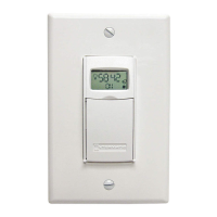
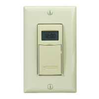
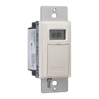
The Intermatic Model E1400 Series is a digital auto shut-off timer designed for various electrical loads, offering convenient control and energy savings. It functions by automatically turning off connected devices after a user-defined period, preventing unnecessary power consumption.

Function Description

The timer operates by allowing users to set a specific duration for which a connected load will remain powered ON. Once this duration expires, the timer automatically shuts off the load. This functionality is particularly useful for applications where devices need to operate for a set time, such as lighting, fans, or other electrical equipment, ensuring they are not left on indefinitely. The timer can be configured for single-switch setups, where it directly controls a load, or for 3-way switch setups, allowing control from multiple locations. In a 3-way setup, a remote switch can be used to toggle the timer ON/OFF or to restart a countdown without cycling the power. The timer also supports multi-switch setups, enabling multiple timers to be mounted adjacently without derating.

Usage Features

The timer features a user-friendly interface with a keypad for setting and operating. To turn the timer ON, users simply press the ON/OFF button on the cover. The display will then show the remaining time until shut-off, along with an ON light bulb icon indicating that the load is powered. Pressing the ON/OFF button again will turn the timer OFF.

Setting the timer interval is straightforward. Users can press and hold the "+" and "-" buttons simultaneously to enter the setting mode. The display will show various time intervals, from 1 second up to 24 hours, which can be fine-tuned using the "+" or "-" buttons. Once the desired time is set, the display confirms the selection and saves it.

The timer includes several special operating tips. Users can check the current timer setting by pressing the "+" or "-" button. If the timer is locked, settings cannot be adjusted. However, if unlocked, users can adjust the timer setting after turning it OFF. A "Pause" function allows users to temporarily suspend a countdown in progress, with flashing pause bars on the display. Pressing "Pause" again resumes the countdown.

For situations requiring a quicker shut-off, users can shorten a countdown by pressing and holding the "-" or ON/OFF button until the desired time is displayed. To lengthen a countdown, users can press and hold the "+" button. If the timer is locked, lengthening is limited to the programmed setting. If unlocked, it can be increased up to 24 hours. A convenient feature is the ability to restart a countdown without powering off the controlled circuit by quickly pressing the cover twice. This is useful for devices like discharge lighting or refrigeration equipment that should not cycle off completely.

The timer also offers a "Warning" option, which can be configured to provide alerts before shut-off. Options include "Off" (no warning), "Beep" (three beeps every 30 seconds starting 3 minutes before shut-off, with a bell icon on the display), "Flash" (controlled lights flash once 3 minutes before shut-off, with a sunburst icon), or "All" (both beep and flash, with both icons displayed).

A "Locking" option provides security by preventing unauthorized changes to the timer settings. Options include "None" (no locking), "Pause" (users cannot use the Pause function), "Time" (users can review but not change the time setting, though they can adjust a running countdown within the locked shut-off setting), and "All" (both pause and setting changes are locked).

Maintenance Features

The timer is powered by a single lithium CR2 battery, which operates the ON/OFF function and maintains the display. The screen will flash "BATT" and "REPL" when the battery is low, indicating it needs replacement. The battery can be changed without removing AC power, and the timer settings remain in memory indefinitely even without battery or AC power. To test the battery, pressing the ON/OFF button should result in an audible "click." It is crucial to replace the battery as soon as the "BATT" and "REPL" messages appear to prevent leakage and potential damage to the timer. Used batteries should be disposed of promptly according to local regulations, and the battery should be kept away from children.

Intermatic EI400WC Specifications

General IconGeneral
TypeElectronic Timer
Voltage120 VAC
ProgrammableYes
Number of Programs7
DisplayLCD
Horsepower1/2 HP
Amperage15A
EnclosurePlastic
Battery BackupYes
MountingWall

Related product manuals