SPECIFICATIONS AND OTHER INFORMATION
INSTALLATION
USEFUL INFORMATION
1. Radio Receivers are sensitive to heat. Avoid
mounting them above heater, air conditioner
or exposed to afternoon sun.
2. The higher the Receiver Module, the longer its
range. For good range and reliable reception, install
modules as high as practical above ground level with
antenna at top.
3. Large metal objects divert radio signals. Avoid
mounting Receiver Modules on metal wall, fence
or near large metal objects.
4. Environmental conditions could effect the operation
of the remote control system. For example, in rain
the range may be less than normal.
5. Certain electric equipment like brush type motors
or electronic gas heater igniters emit radio signals
and can effect the function of the Receiver Module.
Avoid mounting modules near such equipment.
6. To prevent electronic interference, install Receiver
Modules at least 3 feet apart.
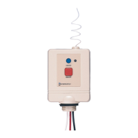
A. ON/OFF Switching Application
- use Model RC613
Make sure the intended load is within the capacity of the
Module, see ratings on page 1 and other choices on page 4.
1. Attach RC613 Receiver Module to the top of an outdoor grade
junction bo
x. Mak
e sur
e the assemb
l
y is raintight.
2. Select the proper location (see Useful Information above) and
install Receiver assembly on a vertical surface or other support,
using har
d
ware, suitable for the purpose.
3. Prepare the necessary conduit runs as required by the installation
layout and pull-in the specified conductors.
4. Follow wiring diagram A on the right, make wire connections
as shown.
5. Turn ON power and test installation, using the ON/OFF button
on f
ace of the Recei
v
er Module
. Re
place junction box cover,
mak
e sur
e the installa
tion is secur
e and raintight.
6. Set code, see Operating Instructions on page 3.
2
*Ground connections may or may not be as shown.
Diagram
A