Printed in U.S.A.
462 01 1101 01 07−29−09
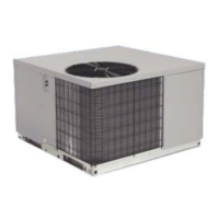
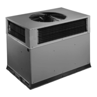
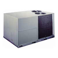
PACKAGED GAS / ELECTRIC UNITS
Installation Instructions
PGF3 Series
Code: PGF3
International Comfort Products, LLC
Lewisburg, TN. 37091
TABLE OF CONTENTS
UNIT DIMENSIONS 2. . . . . . . . . . . . . . . . . . . . . . . . . . . . . . . . . . . . . . . . .
SAFE INSTALLATION REQUIREMENTS 3. . . . . . . . . . . . . . . . . . . . . . . . .
LOCATING THE UNIT 4. . . . . . . . . . . . . . . . . . . . . . . . . . . . . . . . . . . . . . .
CLEARANCES 4. . . . . . . . . . . . . . . . . . . . . . . . . . . . . . . . . . . . . . . . . . . .
INSTALLATION 4. . . . . . . . . . . . . . . . . . . . . . . . . . . . . . . . . . . . . . . . . . . .
GROUND LEVEL INSTALLATION 4. . . . . . . . . . . . . . . . . . . . . . . . . . . . . .
HOISTING 5. . . . . . . . . . . . . . . . . . . . . . . . . . . . . . . . . . . . . . . . . . . . . . . .
DOWNFLOW CONVERSION 5. . . . . . . . . . . . . . . . . . . . . . . . . . . . . . . . . .
HEATING VENT ASSEMBLY 5. . . . . . . . . . . . . . . . . . . . . . . . . . . . . . . . . .
CONDENSATE DRAIN 5. . . . . . . . . . . . . . . . . . . . . . . . . . . . . . . . . . . . . . .
COMBUSTION BLOWER PIPE INSTALLATION 5. . . . . . . . . . . . . . . . . . . .
PRE-EXISTING COMMON VENT CHECK 5. . . . . . . . . . . . . . . . . . . . . . . . .
GAS SUPPLY AND PIPING 6. . . . . . . . . . . . . . . . . . . . . . . . . . . . . . . . . . .
ORIFICES 7. . . . . . . . . . . . . . . . . . . . . . . . . . . . . . . . . . . . . . . . . . . .
ELECTRICAL WIRING 8. . . . . . . . . . . . . . . . . . . . . . . . . . . . . . . . . . .
DUCTWORK 10. . . . . . . . . . . . . . . . . . . . . . . . . . . . . . . . . . . . . . . . .
FILTERS 10. . . . . . . . . . . . . . . . . . . . . . . . . . . . . . . . . . . . . . . . . . . .
AIRFLOW ADJUSTMENT 11. . . . . . . . . . . . . . . . . . . . . . . . . . . . . . .
START-UP PROCEDURES 12. . . . . . . . . . . . . . . . . . . . . . . . . . . . . .
GAS PRESSURES 12. . . . . . . . . . . . . . . . . . . . . . . . . . . . . . . . . . . . .
HEATING START-UP PROCEDURES 13. . . . . . . . . . . . . . . . . . . . . .
OPERATION 14. . . . . . . . . . . . . . . . . . . . . . . . . . . . . . . . . . . . . . . . .
MAINTENANCE 14. . . . . . . . . . . . . . . . . . . . . . . . . . . . . . . . . . . . . . .
INSPECTION AND CLEANING 16. . . . . . . . . . . . . . . . . . . . . . . . . . . .
RIGGING 19. . . . . . . . . . . . . . . . . . . . . . . . . . . . . . . . . . . . . . . . . . .
WIRING DIAGRAMS 20 - 21. . . . . . . . . . . . . . . . . . . . . . . . . . . . . . . .