Do you have a question about the International comfort products DLF4A6 and is the answer not in the manual?
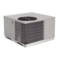
| Brand | International Comfort Products |
|---|---|
| Model | DLF4A6 |
| Type | Air Conditioner |
| SEER Rating | Up to 16 SEER |
| Refrigerant Type | R-410A |
| Voltage | 208/230V |
| Phase | 1 |
| Dimensions (Outdoor Unit) | Varies by model |
| Weight (Outdoor Unit) | Varies by model |
Procedure for evacuating the system using a vacuum pump.
Method using a vacuum pump capable of pulling 500 microns.
Alternate method for systems not containing liquid water.
ON/OFF, MODE, TEMP, FAN controls for basic operation.
Horizontal Swing, X-FAN, TIMER, TURBO, SLEEP, LIGHT functions.
Explains Transmission, Mode, Fan Speed, and Sleep indicators.
Covers Temperature, HEALTH/SAVE, and Battery status displays.
Describes working conditions and cooling process.
Describes working conditions and heating process.
Conditions and process for entering defrost mode.
Details overload, exhaust temp, communication, module protections.
Covers Cold Air prevention, Fan Mode, and AUTO Mode operations.
Covers overload, sensor malfunctions, and failure displays.
Details ON/OFF, Mode, Temp, Fan, Sleep, Buzzer, Auto, Swing, Display.
Covers Memory, Sensor Detection, Frequency, Discharge Pipe, Input Current controls.
Details Freeze-up, Heating Peak-cut, Defrost, Fan, and Speed controls.
Safety precautions, static/dynamic maintenance, and diagnosis steps.
Warning about electrical shock during servicing.
Explains error codes displayed on indoor/outdoor units.
Lists malfunction codes and repair methods for 9k/12k, 115v.
Lists malfunction codes and repair methods for 12K, 230v units.
Lists malfunction codes and repair methods for 18k-24k, 230v units.
Analysis of common malfunctions and their causes.
Analysis of malfunctions related to refrigerant flow.
Troubleshooting steps for insufficient air circulation.
Troubleshooting for fan and compressor not running.
Troubleshooting for swing fan, water leakage, and abnormal sound.
Details on compressor discharge, overload, and IPM module protections.
Troubleshooting for system overload and voltage-related issues.
Diagnostic process for 09 & 12K models.
Flowchart for troubleshooting system faults.
Main check points for compressor and IPM faults.
Flowchart for IPM, out-of-step, and over-current faults.
Detailed flowchart for troubleshooting specific faults.
Troubleshooting for high temp/overload protection.
Flowchart for diagnosing high temp/overload issues.
Diagnosis for outdoor unit start-up failures.
Flowchart for diagnosing start-up failures.
Diagnosis for compressor out-of-step issues.
Flowchart for compressor synchronization diagnosis.
Diagnosing overload and discharge malfunctions.
Flowchart for overload/discharge malfunction diagnosis.
Diagnosis for PFC faults in the outdoor unit.
Flowchart for diagnosing PFC faults.
Diagnosis for communication malfunctions.
Flowchart for diagnosing communication issues.
Instructions for 18 & 24K models regarding malfunctions.
Diagnosis for capacitor charging malfunctions.
Flowchart for capacitor charging fault diagnosis.
Outdoor unit malfunction indicator status and detection.
Detailed flowchart for IPM, compressor faults.
Checks outdoor unit in cooling and indoor in heating mode.
Flowchart for diagnosing high temp/overload issues.
Diagnosis for outdoor unit start-up failures.
Flowchart for diagnosing start-up failures.
Diagnosing compressor synchronization issues.
Flowchart for compressor synchronization diagnosis.
Diagnosing overload and discharge malfunctions.
Flowchart for overload/discharge malfunction diagnosis.
Diagnosis for communication malfunctions.
Flowchart for diagnosing communication issues.
Key detection points for outdoor communication circuit.
Overview of external features.
Procedure for removing indoor unit air filters.
Procedure for removing the front panel of the indoor unit.
Procedure for removing the electric box cover.
Procedure for removing the front case assembly.
Procedure for removing the vertical louver.
Procedure for removing the electrical box.
Procedure for removing the fan motor signal wire.
Procedure for disconnecting refrigerant piping.
Procedure for removing the heat exchanger.
Loosen screws, widen piping, pull heat exchanger.
Remove cross flow blade, fan motor, and bearings.
Procedure to remove the motor sub-assembly and fan motor.
Overview of features and procedure for removing the top panel.
Steps to remove grille, front panel, and side plates.
Remove fan motor, electrical box, and partition plate.
Procedure for removing the compressor.
Overview of features and procedure for removing air filters.
Steps for opening/closing front panel and service cover.
Procedure for removing front grille and electrical box.
Remove piping fixture, motor pressure plate, and shaft cushion.
Procedure to remove top cover, handle, damper, and valve cover.
Remove grille, front panel, right side plate, fan motor.
Remove electric box and partition plate.
Remove sound blanket and four-way valve coil.
Procedure for removing compressor and condenser sub-assemblies.
Overview of features and procedure for removing air filters.
Steps for removing front panel and service cover.
Procedure for removing front grille and electrical box.
Remove piping fixture, guard grille, pressure plate, and shaft cushion.
Procedure to remove top cover, handle, damper, and valve cover.
Remove grille, front panel, right side plate, and electric box.
Remove axial flow blade, fan motor, reactor, and capacitor.
Remove suction/discharge pipes, capillary/expansion valve, and compressor.