Specification:
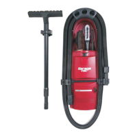
CS8 120 Volt, 7 Amp 60Hz, Weight 5.5 lb
CS-RM 120 Volt, 7 Amp 60Hz, Weight 5.6 lb
Parts List:
Vacuum Cleaner with screws and clamps
Vacuum tool kit: various
Paper template #W608
Read the Safety Instruction on the switch side behind the front panel !
CAUTION: DISCONNECT POWER BEFORE ATTEMPTING TO INSTALL THIS UNIT.
CHECK FOR ANY OBSTRUCTIONS BEHIND THE MOUNTING SURFACE
CS8 and CS-RM with POWER CORD
DO NOT USE WITH EXTENSION CORD
Recessed Installation into Wood or other Hard Surface Walls:
The central vacuum should be mounted so that power supply cord can be plugged directly into a electrical outlet.
Choose a place that is centrally located to maximize the reach with the vacuum hose.
The minimum wall thickness is 3/8” the maximum is 1”.
The cut-out in the wall is 11“ wide X 6” high and requires a minimum depth of 6”
Very important: If you installed the vacuum in a very small cabinet you must make provisions to
exhaust the air from the vacuum out of the cabinet.
Option 1: Cut a hole in the cabinet a minimum 3”, attach a louver to cover the hole.
Option 2: Use our part #B560 exhaust fitting with a 2” diameter flex-hose to guide
the warm air to the outside, or to where ever you prefer. See page 8 options
Step A. Tape the paper template against the surface at a comfortable operating height
Step B. With a skill saw cut along the dotted line of the paper template.
Step C. Slide the unit, power cord in first, into the opening and secure by tightening the four attached
screws with the “clamps”. Do not over-tighten.
Step D. Check to be sure dust bag and motor filter are in place.
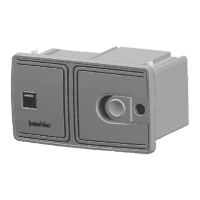
Step E. Install the remote vacuum valve (CS-RM model only). Then route the flex-hose from the valve to the vacuum.
Step F. From the remote vacuum valve install 2 yellow 20 gage, UL approved (AVLV2) rated minimum 300volt, 95 C,
wires (24 volt line) along the flex-hose to the bottom of the vacuum to the 2 yellow pigtails.
Secure the wires with “ty-wraps” to the flex-hose.
Connect yellow wires with butt connectors outside the Housing.
CS8-F and CS-RM-F Hard Wired
Same wall installation procedure as above , steps A through D.
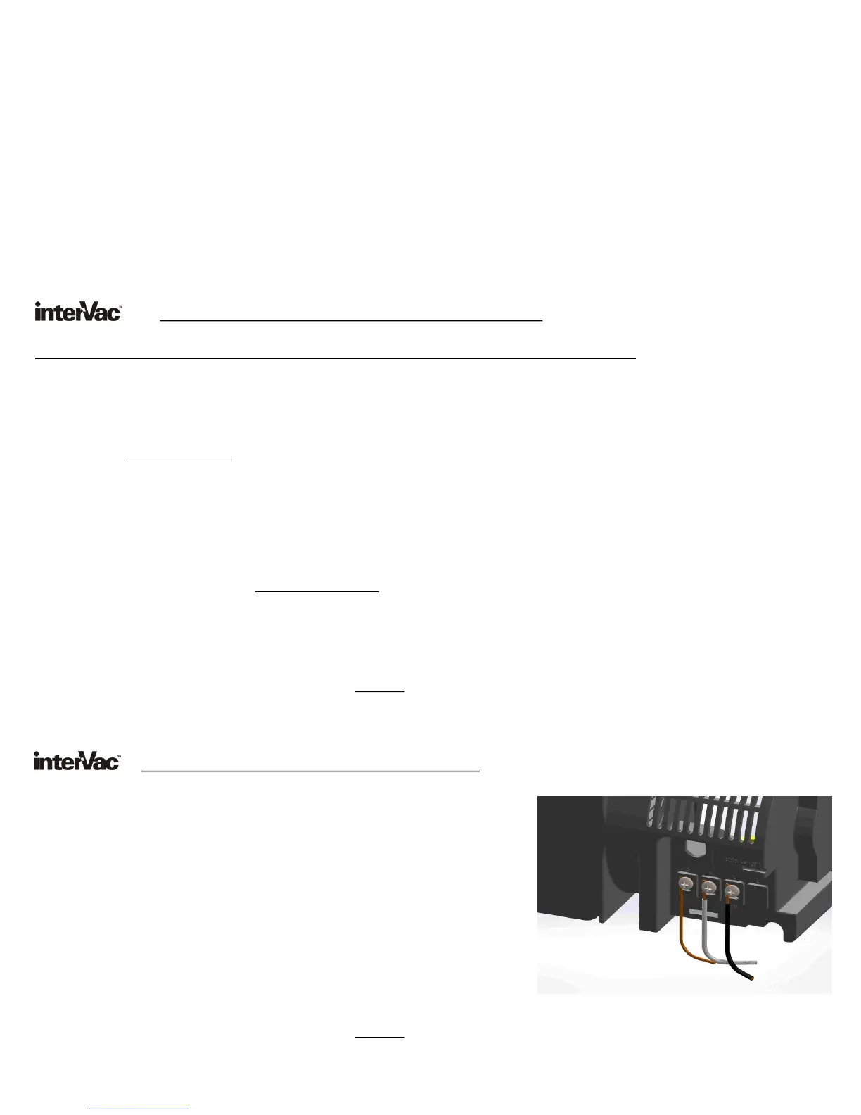
Step 1. From the Circuit Breaker run a 14 gage Romex cable to the
back of the vacuum.
Step 2. Slide the wire cover (supplied) over the cable.
Step 3. Strip the 3 wires about 5/8” and attach the Black to “L”, the white
wire to “N” (neutral) and the GROUND wire to the “G” connection.
Step 4. Press the wire cover into the 2 slots above and below
the cable connections. Then attach the small screw.
Step 5. Install the remote vacuum valve (CS-RM model only). Then route the
flex-hose from the valve to the vacuum.
Step 6. From the remote vacuum valve install 2 yellow 20 gage, UL
approved (AVLV2) rated minimum 300volt, 95 C, wires
(24 volt line) along the flex-hose to the bottom of the vacuum to the 2 yellow pigtails.
Secure the wires with “ty-wraps” to the flex-hose.
Connect yellow wires with butt connectors outside the Housing.
3
3
 Loading...