87PO
SAVE THESE INSTRUCTIONS
English
(87PO) METAL FRAME POOL ENGLISH 7.5” X 10.3” PANTONE 295U 06/02/2020
Page 12
POOL SETUP
(
continued
)
YoumayhavepurchasedthispoolwiththeIntexKrystalClear™filterpump.Thepumphasitsown
separate set of installation instructions. First assemble your pool unit and then set up the filter pump.
Estimatedassemblytime30-60minutes.(Notetheassemblytimeisonlyapproximateandindividual
assemblyexperiencemayvary.)
1. Liner preparation
• Findaflat,levellocationthatisfreeandclearofstones,branchesorothersharpobjectsthatmay
puncture the pool liner or cause injury.
• Openthecartoncontainingtheliner,joints,legs,etc.,verycarefullyasthiscartoncanbeusedtostore
the pool during the winter months or when not in use.
• Takeoutthegroundcloth
(7)
(ifincluded)andspreaditover
the cleared area. Then take out the liner
(5)
and spread it
outoverthegroundcloth,withthedrainvalvedirected
towardsthedrainingarea.Placethedrainvalveaway
from the house. Allow the sun to warm up the liner before
inserting the beams
(4)
intothesleeveopenings.
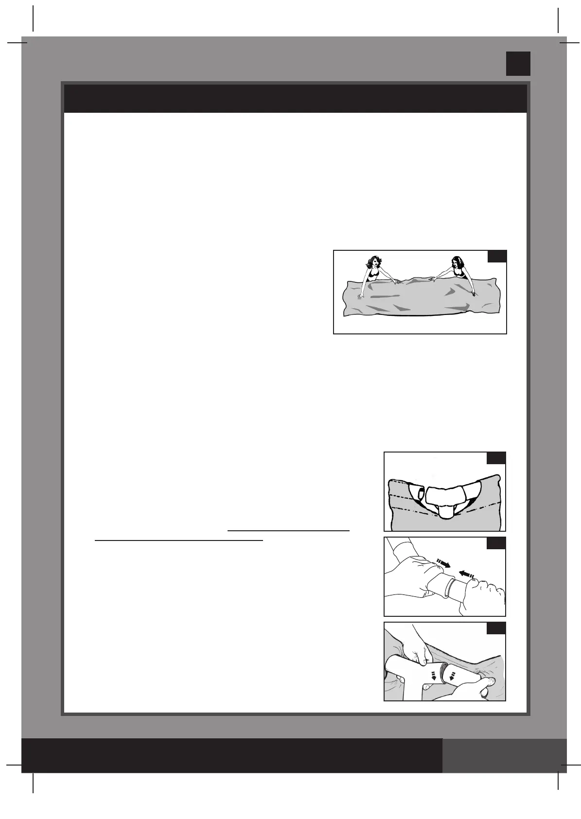
IMPORTANT: Always set up the pool unit with at least
2 persons. Do not drag the liner across the ground as
this can cause liner damage and pool leakage (see
drawing 1).
• Duringthesetupofthispoolliner,pointthehoseconnectionsoropeningsinthedirectionoftheelectric
powersource.Theouteredgeofthepoolshouldbewithinreachofthepump’selectricalconnection.
2. Horizontal beams assembly
• Theframepool’slegs
(2)
and beams
(4)
fallintotwogroups.Thelargerdiametersarethehorizontal
beamsthatareslid(pushed)intothesleeveopeningsatthetopoftheliner.Thesmallerdiametersare
theverticallegs.BoththeselegsandbeamsfitintotheT-joints
(1)
.
NOTE:
Sprinkle some talcum powder over the horizontal beams before sliding them into the pool
liner sleeve. This will make removal of the beams from the liner easier during the disassembly
of the pool.
• Startingatanylocation,butalwaysworkinginthesamedirection,
pushthehorizontalbeamintothesleeve.Oncethebeamiscentered
take one of the T-joints and attach the joint to one end of the beam.
Push the beam firmly into the T-joint. Repeat this procedure in a
circularfashionuntilallthebeamsandjointshavebeenconnected
(see drawings 2.1 & 2.2)
.
NOTE:
It’simportanttostartfrom
one location and work in the
same direction until the last attachment.
Donotstartfrommultiple
locations as this will make the connections difficult for the last few
beams and joints.
The last joint connection may be difficult to complete. You can
do it though, if you first simultaneously raise the last joint and
beam about 2 inches (5 cm). Now insert the beam into the joint
while lowering the pieces into position. The beam will easily
slide into the joint (see drawing 2.3). Ensure that the last joint
is fully connected before proceeding to connecting the legs.
1
5
2.3
1
2.2
4
1
2.1
4
 Loading...