2
WALKER TRAY Part No. 1089635
INSTALLING SNAP SUPPORTSINSTALLING SNAP SUPPORTS
INSTALLING SNAP SUPPORTSINSTALLING SNAP SUPPORTS
INSTALLING SNAP SUPPORTS
- SINGLE RELEASE WALKERS- SINGLE RELEASE WALKERS
- SINGLE RELEASE WALKERS- SINGLE RELEASE WALKERS
- SINGLE RELEASE WALKERS
ONLY (FIGURE 2)ONLY (FIGURE 2)
ONLY (FIGURE 2)ONLY (FIGURE 2)
ONLY (FIGURE 2)
NOTE: Refer to the WARNINGS in the SAFETY
SUMMARY of this instruction sheet.
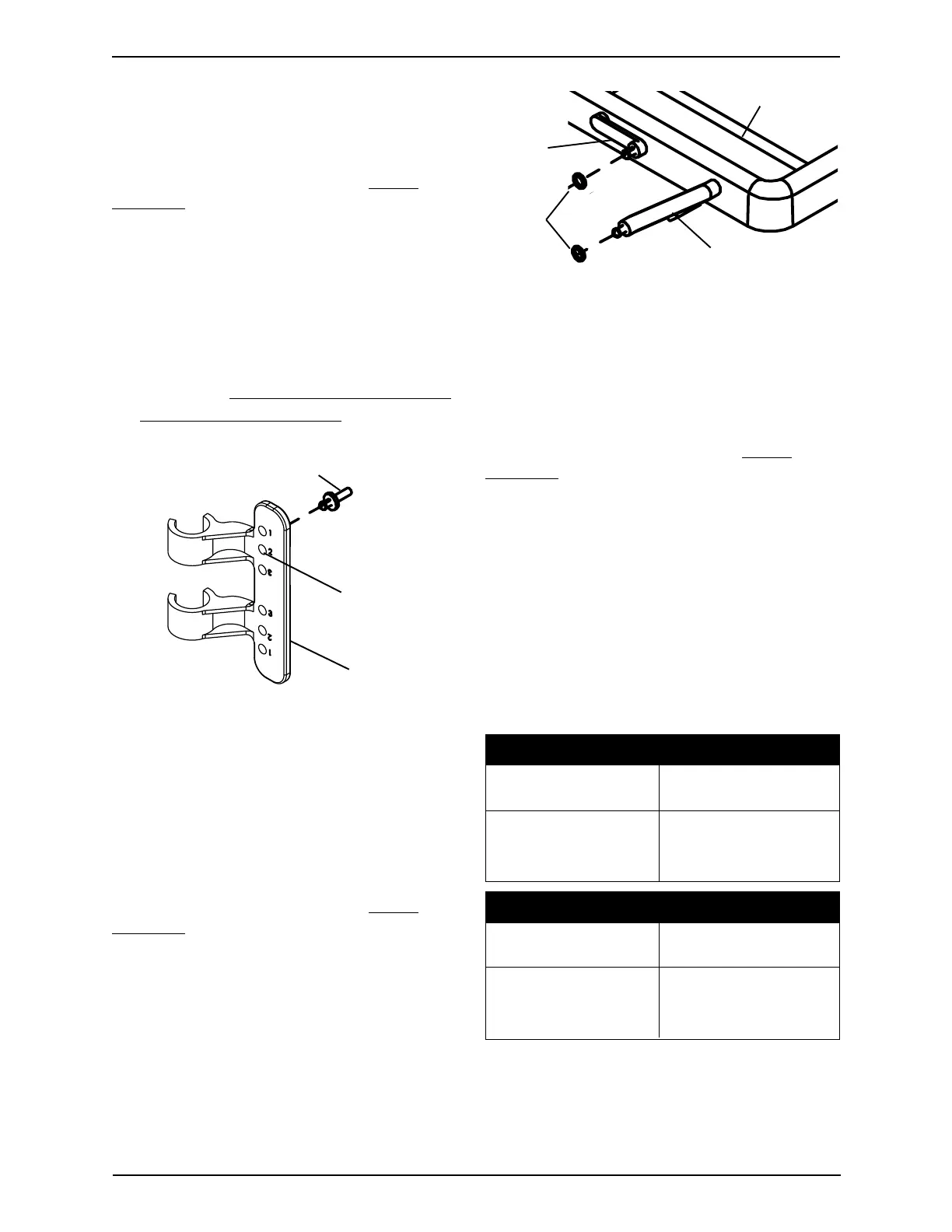
1. Locate the upper hole in the tray side
brace that is marked "2".
2. On the INSIDE of the tray side brace,
attach the snap support into the location
determined in STEP 1. Refer to FIGURE 2.
3. Repeat for opposite tray side brace.
4. Proceed to
INSTALLING THE O-RINGS
ONTO THE TRAY LINKS in this instruc-
tion sheet.
ATTACHING THE WALKERATTACHING THE WALKER
ATTACHING THE WALKERATTACHING THE WALKER
ATTACHING THE WALKER
TRAY TO THE TRAY SIDETRAY TO THE TRAY SIDE
TRAY TO THE TRAY SIDETRAY TO THE TRAY SIDE
TRAY TO THE TRAY SIDE
BRACES (FIGURE 4)BRACES (FIGURE 4)
BRACES (FIGURE 4)BRACES (FIGURE 4)
BRACES (FIGURE 4)
NOTE: Refer to the WARNINGS in the SAFETY
SUMMARY of this instruction sheet.
1. Place the walker tray onto the walker with
the walker tray links positioned towards
the front of the walker as shown in
FIGURE 4.
2. Insert and lock the tray links into the
following holes of the tray side brace as
shown in FIGURE 4.
NOTE: There are two (2) sizes of tray links. Refer to
the chart below and FIGURE 4 to determine tray link
size.
SHORT TRAY LINK POSITIONING
FOR DUAL RELEASE FOR SINGLE RELEASE
WALKERS WALKERS
SECOND HOLE TOP HOLE
FROM TOP (MARKED "1")
(MARKED "2")
LONG TRAY LINK POSITIONING
FOR DUAL RELEASE FOR SINGLE RELEASE
WALKERS WALKERS
FIFTH HOLE FOURTH HOLE
FROM TOP FROM TOP
(MARKED " ")(MARKED "3")
3. Repeat STEP 2 for the opposite tray links.
FIGURE 2 - INSTALLING SNAP
SUPPORTS - SINGLE RELEASE
WALKERS ONLY
Long Tray Link
Short
Tray
Link
O-Rings
Walker Tray
FIGURE 3 - INSTALLING O-RINGS
ONTO THE TRAY LINKS
INSTALLING THE O-RINGSINSTALLING THE O-RINGS
INSTALLING THE O-RINGSINSTALLING THE O-RINGS
INSTALLING THE O-RINGS
ONTO THE TRAY LINKSONTO THE TRAY LINKS
ONTO THE TRAY LINKSONTO THE TRAY LINKS
ONTO THE TRAY LINKS
(FIGURE 3)(FIGURE 3)
(FIGURE 3)(FIGURE 3)
(FIGURE 3)
NOTE: Refer to the WARNINGS in the SAFETY
SUMMARY of this instruction sheet.
1. Install the four (4) O-rings over the ends
of the walker tray links as shown in
FIGURE 3.
Upper Hole
Marked "2"
Tray Side
Brace
Snap Support
2