Do you have a question about the InvenSense INMP441 and is the answer not in the manual?
| Interface | I2S |
|---|---|
| Operating Temperature | -40 °C to +85 °C |
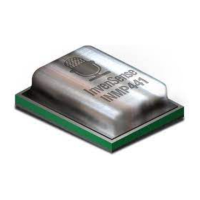
| Package | LGA |
| Type | Digital MEMS |
| Frequency Response | 60 Hz - 15 kHz |
| Sensitivity | -26 dBFS |
| Power Supply Voltage | 1.8 V to 3.6 V |
| THD | 0.5% |
Lists various applications for the microphone.
Highlights key characteristics and benefits of the microphone.
Explains the dBFS unit for digital microphone sensitivity.
Details the normal, standby, and power-down operational modes.
Describes the output behavior during initial power-up.
Describes the behavior of the SD output pin.
Specifies the length of data words in bits.
Details the I2S data format and MSB-first convention.
Describes the high-pass filter for removing low frequencies.
Describes the low-pass filter for noise reduction.
Recommends capacitor placement for power supply stability.
Details how to handle the microphone with automated equipment.
Specifies requirements for solder paste and reflow profiles.
Provides guidance on cleaning procedures after assembly.
