Do you have a question about the Invivo Expression 865214 and is the answer not in the manual?
Details the manual's sections, covering introduction, unpacking, overview, installation, power-up, testing, and parts.
Explains conventions for Warnings, Cautions, and Notes to ensure user safety and proper understanding.
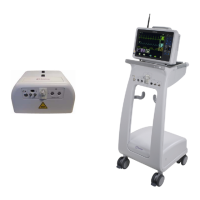
Lists primary components of the Cart configuration, including DCU, WPU, WECG, and WSpO2 modules.
Lists primary components of the PMC configuration, including WPU, DCU, WECG, and WSpO2 modules.
Describes interchangeable battery operation for Cart, PMC, and DCU, including installation and removal.
Detailed steps for installing/removing batteries in PMC, Cart, and DCU, with safety precautions.
Explains battery operation for WECG/WSpO2 modules, including installation and removal.
Provides essential safety guidelines for battery usage, handling damaged batteries, and maintenance.
Details charging instructions for Cart, PMC, DCU, and wireless module batteries.
Covers power supply installation, warnings for placement, and extension cords.
Specific instructions/warnings for 989803169201 power supply, emphasizing MR safety distance.
Installation details/warnings for 989803168201 power supply, including I/O configuration.
Warnings/instructions for installing/setting up the Cart configuration in the MR room.
Warnings/instructions for installing/setting up the PMC configuration, emphasizing MR safety.
Instructions for installing and operating the DCU, including configuration and safety.
Instructions for DCU installation on Cart, with MR safety warnings for ferrous materials.
Procedures for safely disconnecting system from AC power via cord or DC power.
Outlines test timing based on service events like installation, repairs, or upgrades.
Checklist for visual, power-on, performance, safety tests with procedures and results.
Detailed performance tests for WECG, WSPO2, NIBP, and invasive pressure.
Advises on testing frequency for performance assurance and preventative maintenance.
Describes test process, equipment requirements, initial power-up, and operational tests.
Lists necessary test equipment, simulators, and accessories for system testing.
Details initial AC power-up, verifying indicator LEDs on DCU and Cart/PMC.
Guides through operational tests for system functionality, covering communication and parameter performance.
Verifies communication between DCU, WPU, WECG, WSPO2 using system icons.
Setup/verification for WECG communication, including simulator connection and trace verification.
Procedure for testing WSpO2 communication, including probe connection and waveform verification.
Covers NIBP tests: leak tests, offset verification, calibration accuracy.
Verifies NIBP calibration accuracy by checking pressure readings against simulator values.
Tests adult overpressure, verifying "OVER PRES" display at specific pressure levels.
Tests neonatal overpressure, verifying alarm activation and "OVER PRES" display.
Tests adult NIBP cuff for inflation, deflation, and pressure numeric display.
Tests adult NIBP with dead man cuff, verifying zero reading at cycle end.
Tests neonatal BP, verifying cuff inflation, deflation, and numeric display.
Tests neonatal NIBP with dead man cuff, verifying zero reading at cycle end.
Tests adult NIBP leak time-out, verifying pump shut-off and error message.
Tests neonatal NIBP leak time-out, verifying pump shut-off and error message.
Verifies calibration error response, checking pump behavior and error message.
Tests invasive pressure accuracy against simulator, checking readings within tolerances.
Verifies Agents module functionality, including flow tests and occlusion detection.
Specific tests for Agents module, checking flow rates and CO2 occlusion messages.
Verifies O2 sensor expiration and calibration, ensuring correct ambient oxygen readings.
Verifies ETCO2 flow test, including zero calibration and occlusion message display.
Tests respiration monitoring, verifying display of consistent respiration rate.
Verifies temperature monitoring, ensuring accuracy within ambient temperature limits.
States electrical safety verified to IEC 60601-1-1 standards.
Instructions for removing/replacing WPU from the Cart.
Steps for removing WPU from Cart, involving screws, covers, and cables.
Steps for replacing WPU into Cart, including antenna, battery, and shield.
Critical steps for configuring network after WPU exchange.
How to set network channel options based on DCU indicator.
Instructions for disabling unpurchased options on exchanged assemblies.
Instructions for removing/replacing WPU from the PMC.
Steps for removing WPU from PMC, involving cover, O2 door, and cables.
Steps for replacing WPU into PMC, including securing WPU and PCU.
Critical steps for configuring network after PMC WPU exchange.
Lists non-exchangeable service parts with numbers and descriptions.
Lists exchangeable service parts, including WPUs and DCUs.
Lists parts for system preventative maintenance, by system type.
Details service numbers, part numbers, and repair strategies for parts.
| Brand | Invivo |
|---|---|
| Model | Expression 865214 |
| Category | Medical Equipment |
| Language | English |