(*) Each bus line may have between 1 and 5 sensors. The maximum number of S201A sensors managed by a
single control unit is 6.
When the control unit is inside of the chain, it is necessary to exclude the termination resistance on the control
unit itself using the DIP Switch “A”.
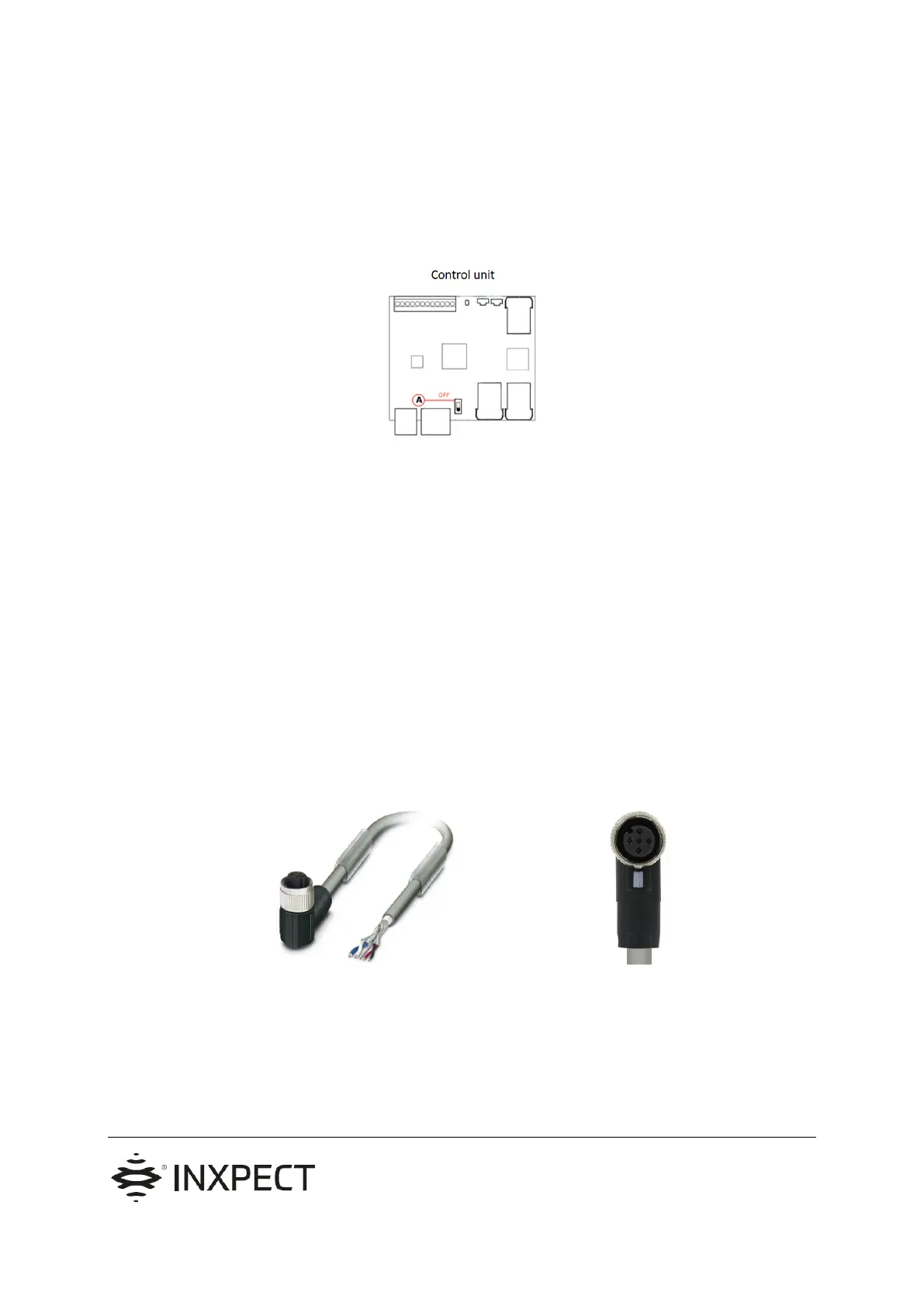
3. Cable between the control unit and the first
sensor
The cable between the control unit and the first sensor must have an M12 female connector “A-coded” in order to
plug into the first sensor, and free wires to plug in the control unit screw terminal.
The connector may be straight or 90° angled. In case of installation with the sensor anchored to a vertical plane
the 90° angled version is suggested (example: wall installation).
Example picture:
 Loading...