EasyManua.ls Logo

ION Damper Control - User Manual

ION Damper Control
8 pages
Print Icon
To Next Page IconTo Next Page
Loading...
SYST0101ZP
Ion™ Damper Control
Installat i on and Start---Up Instruct i ons
A97040I
NOTE: Read the entire instruction manual before starting the
installation.
SAFETY CONSIDERATIONS
Improper installation, adjustment, alteration, service, maintenance,
or use can cause explosion, fire, electrical shock, or other
conditions which may cause death, personal injury or property
damage. Consult a qualified installer, service agency or your
distributor or branch for information or assistance. The qualified
installer or agency must use factory--authorized kits or accessories
when modifying this product. Refer to the individual instructions
packaged with the kits or accessories when installing.
Follow all safety codes. Wear safety glasses, protective clothing,
and work gloves. Have a fire extinguisher available. Read these
instructions thoroughly and follow all warnings and cautions
included in literature and attached to the unit. Consult local
building codes and the current edition of the National Electrical
Code (NEC) NFPA 70. In Canada, refer to the current editions of
the Canadian Electrical Code CSA C22.1.
Recognize safety information. When you see this symbol
on
the unit and in instructions or manuals, be alert to the potential for
personal injury. Understand the signal words DANGER,
WARNING,andCAUTION. These words are used with the
safety--alert symbol. DANGER identifies the most serious hazards,
which will result in severe personal injury or death. WARNING
signifies hazards, which could result in personal injury or death.
CAUTION is used to identify unsafe practices, which may result
in minor personal injury or product and property damage. NOTE
is used to highlight suggestions which will result in enhanced
installation, reliability, or operation.
INSTALLATION CONSIDERATIONS
Before the actual installation of a zoning system can begin,
decisions need to be made to determine the number and location of
zones and sensors. This affects duct and damper selections.
See the Iont System Zoning Design Guide for more
information on specifying and designing zoning systems.
This instruction covers the physical installation and start up of the
Iont Damper Control. Use this instruction to guide the actual
installation process after all the air side decisions have been made.
One Damper Control is capable of handling up to four zones of
operation. When greater than four zones are required, a second
Damper Control Module is needed for zones 5 through 8 (8 zones
maximum).
S NOTE: The Iont Zoning System IS NOT compatible with all
ICP communicating indoor equipment. For example,
(F,G)9MV and (F,G)8MV two--stage, communicating gas
furnaces are NOT compatible with the Iont Zoning System.
See the Ion t System Control product data for more
information.
S NOTE: Only use modulating dampers provided by ICP for
use with the Iont Zoning System. Dampers provided by
other companies are NOT compatible with the Iont Zoning
System.
S NOTE: Observerr System accessories, except for certain
dampers (see damper list), are NOT compatible with the Ion
Zoning System.
Use the Observer r Zoning System, or equivalent, for
non--compatible indoor units, such as non--communicating
indoor units, or the (F,G)9MV and (F,G)8MV gas furnaces. The
Observer r ZoningSystemmayalsobeusedinretrofit
applications where it is impractical to change existing zone
dampers.
S Install the Iont System Control and Remote Room Sensors in
non--condensing areas with ambient temperatures between 32F
and 120F. Install dampers and the Iont Damper Control in
non--condensing areas with ambient temperatures between --4F
to 158F(--20 to 70C).
S A TXV is required on the indoor coil when used with all
residential split system equipment.
S Proper equipment selection and duct sizing are important in a
zoned system. See the Ion Zoning System Design Guide for more
information.
S DO NOT USE a bypass damper with the Iont Zoning System.
Addition of a bypass will cause improper operation. Airflow
management will be performed by the Iont System Control
algorithms. The Iont System Control will monitor the system
and will maintain proper airflow through the heating / cooling
equipment.
INTRODUCTION
The Iont Zoning System allows air conditioning and heating
equipment to control temperatures and humidity in up to 8 distinct
spaces, or zones, within a building. Each zone has independent
temperature settings. The comfort temperature settings can change
automatically through the use of schedules. This allows the Iont
System to change temperature settings in zones to reflect
occupancy or usage. For example, the end user can condition
bedrooms in a home from 5:00 PM through 7:00 AM or the
kitchen from 3:00 PM through 6:00 PM. The Iont System uses
motorized air volume control dampers (also called zone dampers)
to regulate flow of conditioned air into zones. In this manner, the
system can selectively heat or cool certain portions of a building
depending upon space temperature requirements.
Each zone requires a motorized, modulating zone damper to
control the air supplied to it and a zone sensor to sense temperature
in each zone. There are two types of zone sensors available and
may be used in combination:
S Iont System Control (p/n SYST0101CW) Each installation
has only one Master wall/zoning control. This is the command
center for the entire system. It will typically be located in Zone 1
to sense and control the temperature in this zone. If desired, a
Remote Room Sensor may be used to sense the Zone 1
temperature. This can give the installer some flexibility in locating
the Master Iont System Control wall control to another area.
Question and Answer IconNeed help?

Do you have a question about the ION Damper Control and is the answer not in the manual?

Summary

Safety Considerations

Safety Information and Signal Words

Understand signal words like DANGER, WARNING, CAUTION, and NOTE.

System Introduction and Planning

Compatibility and Requirements

Notes on compatibility with ICP equipment and TXV requirement.

Installation Procedures

Step 1: Equipment & Job Site Check

Inspect equipment for damage or incompleteness before installation.

Step 2: Component Location, Wiring & Safety

Covers electrical safety, wiring compliance, component placement, and wiring considerations.

Component Installation

Install Damper Control, System Control, & Sensors

Instructions for installing the Damper Control, System Control, and Room Sensors.

Zone Damper Installation

Covers damper compatibility, placement, and electrical safety.

Ductwork Installation Types

Instructions for installing dampers in various ductwork types.

Ductwork Damper Installation

Rectangular & Flexible Ductwork

Steps for connecting dampers to rectangular and flexible ductwork.

Fibrous Glass Ductwork Installation

Steps for connecting dampers to fibrous glass ductwork.

Step 5: Final Wiring

System Wiring Diagram Reference

Reference to wiring diagrams for connecting components.

System Wiring Diagrams

Zones 1-4 Wiring Diagram

Diagram showing wiring for zones 1 through 4.

Zones 5-8 Wiring Diagram

Diagram for setting up additional zones 5 through 8.

System Indicators and Configuration

LED Indicators and Fuse Information

Explanation of status LEDs and details about the system fuse.

Additional Zone Setup

Guide for setting up additional zones using a second damper control module.

Power Requirements and Start-up

Information on transformer requirements and system start-up procedures.

Troubleshooting Common Issues

System Power and Communication Problems

Steps to resolve power-up and indoor unit communication errors.

Zone Detection Issues

Steps to resolve issues with zones 5-8 or zones 1-4 not being detected.

Zone Damper Malfunctions

Troubleshooting steps for non-responsive zone dampers.

Overview

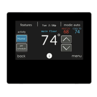
The Ion™ Damper Control (SYST0101ZP) is a key component of the Ion™ Zoning System, designed to manage air conditioning and heating in up to eight distinct spaces or zones within a building. This system allows for independent temperature settings in each zone, which can be automatically adjusted through schedules to reflect occupancy or usage patterns. For instance, a user can set specific conditioning times for bedrooms (e.g., 5:00 PM to 7:00 AM) or the kitchen (e.g., 3:00 PM to 6:00 PM). The Damper Control achieves this by utilizing motorized air volume control dampers, also known as zone dampers, to regulate the flow of conditioned air into each zone, thereby selectively heating or cooling different parts of a building based on space temperature requirements.

Function Description:

The Ion™ Damper Control acts as the central hub for all zone damper and sensor wiring. It communicates with the Ion™ System Control, which is the master wall/zoning control and the command center for the entire system. Each zone requires a motorized, modulating zone damper and a zone sensor to measure temperature. The system supports two types of zone sensors: the Ion™ System Control itself (typically located in Zone 1) and Remote Room Sensors (SYSTXIIRRS01), which are temperature-only sensors. Multiple Remote Room Sensors can be wired in series/parallel for temperature averaging in a zone.

The Damper Control's algorithms perform airflow management, eliminating the need for a bypass damper, which would otherwise cause improper operation. It continuously monitors the system to maintain proper airflow through the heating/cooling equipment.

For systems requiring more than four zones, a second Damper Control Module is necessary to manage zones 5 through 8, with a maximum capacity of eight zones. The two Damper Control Modules communicate via a shared bus connection.

Important Technical Specifications:

  • Compatibility: The Ion™ Zoning System is NOT compatible with all ICP communicating indoor equipment, specifically (F,G)9MV and (F,G)8MV two-stage, communicating gas furnaces. It is also not compatible with Observer® System accessories, except for certain dampers. Only modulating dampers provided by ICP are compatible with the Ion™ Zoning System.
  • Operating Environment: The Ion™ System Control and Remote Room Sensors should be installed in non-condensing areas with ambient temperatures between 32°F and 120°F. The Damper Control and zone dampers can be installed in non-condensing areas with ambient temperatures between -4°F to 158°F (-20°C to 70°C).
  • Damper Capacity: One Damper Control can handle up to four zones. For systems with 5-8 zones, a second Damper Control Module is required. Up to five dampers can be wired in parallel for a single zone output.
  • Power: A 1A automotive type fuse protects the Damper Control from overcurrent on the damper drive outputs. If this fuse fails, the damper wiring should be inspected for shorts. The system is designed to drive only two zone damper outputs at a time, allowing up to eight zones (each with up to five dampers) plus a smart sensor without increasing the size of the system transformer. The transformer provided in the furnace or fan coil is generally sufficient. For increased capacity, a field-installed, Class 2, 24VAC transformer can be used to power the communication system by connecting its C and R terminals to the Damper Control's communication bus.
  • Wiring: Ordinary thermostat wire (shielded cable not necessary) is suitable for wiring. 20 AWG or larger wire is recommended for typical installations, with 18 AWG or larger for lengths over 100 ft. Remote Room Sensors require two conductors, but running four is recommended for future Smart Sensor upgrades. Each damper actuator requires three conductors. The communication bus requires four conductors (DX+, DX-, C, R). Recommended color code: Green (Data A), Yellow (Data B), White (24 VAC Com), Red (24VAC Hot).
  • Sensors: A TXV (Thermostatic Expansion Valve) is required on the indoor coil when used with all residential split system equipment. Leaving Air Temperature (LAT) and Heat Pump Temperature (HPT) sensors are used for diagnostic purposes only and are not required for regular operation, as airflow management is handled by the Ion™ System Control algorithms.

Usage Features:

  • Zoning Capability: Controls up to 8 distinct zones, each with independent temperature settings and schedules.
  • Automated Schedules: Allows for automatic temperature adjustments based on occupancy or usage patterns.
  • Airflow Management: Built-in algorithms manage airflow, eliminating the need for a bypass damper and ensuring proper airflow through HVAC equipment.
  • Sensor Flexibility: Supports both the main Ion™ System Control as a zone sensor and dedicated Remote Room Sensors. Remote Room Sensors can be averaged for more accurate temperature readings in a zone.
  • Diagnostic Indicators: Yellow and Green LEDs on the Damper Control provide status information. Solid LEDs indicate normal operation. A blinking Yellow LED indicates a fault with a two-digit status code (e.g., 16=Communication Failure, 24=Damper Fuse Failed, 45=Board Failure, 46=Low Input Voltage).
  • Damper Alignment: If a damper actuator is removed, it must be properly realigned by rotating the actuator and blade to their closed positions before tightening.

Maintenance Features:

  • Troubleshooting Guide: The manual provides a comprehensive troubleshooting section for common issues such as "Ion™ System Control does not power up," "Indoor Unit Not Found," "Cannot find Zones 5-8," and "Zone dampers do not move."
  • Fuse Protection: A replaceable 1A automotive type fuse protects the damper drive outputs. Regular inspection of damper wiring for shorts is recommended if the fuse fails.
  • Damper Installation Guidelines: Detailed instructions for installing dampers in various duct types (round metal, rectangular metal, round flexible, rectangular fibrous glass) ensure proper operation and longevity. This includes sealing joints, insulating in unconditioned spaces, and positioning actuators to avoid condensation.
  • Wiring Consistency: Emphasizes the importance of consistent wiring for all bus connections to ensure reliable communication.
  • Component Location: Guidelines for locating the Damper Control and sensors to ensure accurate temperature measurement and prevent damage from environmental factors (e.g., condensation, direct heat sources).
  • System Checkout Procedure: Refers to the Installation Instructions for a system checkout procedure to test zoning dampers and verify correct operation.
  • Direct Damper Testing: Dampers can be powered directly with 24VAC across Com and Open, or Com and Close terminals for testing purposes, which helps in ruling out damper malfunctions.

ION Damper Control Specifications

General IconGeneral
BrandION
ModelDamper Control
CategoryControl Unit
LanguageEnglish

Related product manuals