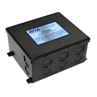
ITS-50R TRANSFER SWITCH
OWNER’S MANUAL
IOTA Engineering Transfer Switches provide automatic
power switching between two or three separate 120/240
volt AC input sources, including powercords, onboard gen-
erators, onboard inverters, or all three. The ITS will sense
the presence of available supplies and automatically se-
lect the proper one.
The ITS can be installed at the electrical entry of the RV
on the line side of the main distribution panel, or it can be
installed on the load side of the panel between the main
panel and a sub panel, allowing switching for either the
entire electrical load or only designated circuits.
INSTALLATION
READ AND FOLLOW ALL SAFETY INSTRUCTIONS
I. DISCONNECT POWER
Make sure the generator is off, the external powercord is
unplugged, and the inverter, if any, is shut off.
II. MOUNTING LOCATION
The ITS mounting location may be on any interior surface
where the unit will be out of direct weather. The chosen
location must be accessible after installation is complete
to facilitate future servicing. If possible, mount the ITS
near the powercord entry or the location of the generator
output. Typical locations include under counter cabinets,
below closet compartments, inside the bed pedestal or
cabinets, overhead cabinets, under-floor storage compart-
ments accessed from the vehicle exterior, etc. CAUTION:
TO PREVENT EXPOSURE TO FOREIGN CONTAMINANTS,
DO NOT MOUNT THE TRANSFER SWITCH IN AN ENGINE
COMPARTMENT, UNDER KITCHEN SINK DRAINS OR WA-
TER PIPES, WITHIN THE BATTERY COMPARTMENT, OR
ANY COMPARTMENT DESIGNED FOR STORAGE OF
FLAMMABLE LIQUIDS SUCH AS GASOLINE.
III. ELECTRICAL PREPARATION
Use knockouts 12, 5, and 6 when installing the ITS-50R.
Do not use knockouts 3, 4, 7, and 8 when preparing the
ITS-50R for installation.
IV. MOUNTING
Mount the ITS-50R with screws through holes provided in
bottom corners of the can. The unit should be screwed to a
solid surface firmly enough to hold its weight during ve-
hicle operation.
V. ELECTRICAL CONNECTIONS
A. Attach an 8 gauge chassis ground wire to the transfer
switch ground bar. A direct access hole to the ground bar is
provided through the enclosure for convenience.
B. Determine proper connections of wire conductors to electrical
terminals. On 120 VAC wiring the ground wire is bare or green,
the neutral wire is white, and the hot wire is black. On 240 VAC
wiring there are two hot wires; one is black, and the other is red.
C. Strip the outer jacket from all of the incoming cables. Strip
insulation from all ends of the copper conductors. Insert cables
through clamps in openings. Do not tighten cable clamps at this
time.
D. Route internal ground wires around lower area of enclosure
and secure to ground wires away from electrical contacts on
components to avoid the possibility of electrical short-circuit.
E. Connect the ground wires to the ground bar. Tighten terminals
to a minimum of 20 inch-pounds.
F. Connect the neutral (white) wire connections.
G. Connect the hot wire(s). If there is a black wire and a red wire
(for 240 VAC), it does not matter which is hot 1 and which is hot 2.
H. In some applications it may be desirable to feed a 120 volt
supply, such as an inverter, into both hot legs of a transfer switch,
so that the 120 volt supply can operate the entire RV load. Al-
though discretion is advised in designing this into the system, it
is acceptable,
as long as the connection to both hot legs is ac-
complished on the input side of the transfer switch
. To do this,
connect the hot from the 120 volt supply, such as an inverter, to
hot 1, then attach a jumper wire of the same gauge from hot 1 to
hot 2. Consideration should be given to the following:
• All the load must be 120 volt; you cannot operate a 240
volt load from a 120 volt supply.
• There may be a load which would be undesirable to run
from this particular 120 volt supply; that load should be
isolated when the 120 volt supply is operating. The ITS-
30R is sometimes used as a ‘lock-out’ switch to prevent
specific loads from being operated from designated sup-
plies. Example: preventing a battery charger or air condi-
tioner from running from an inverter, yet operating from
generator or powercord.
I. Tighten cable clamps on switch enclosure.
J. Attach lid. The lid is designed to snap on and should not open
without deliberate effort.