Do you have a question about the iPA 9107B and is the answer not in the manual?
Lists the components and accessories provided with the Electric Brake Force Meter kit, including soft case and cables.
Details the vehicle compatibility of the Electric Brake Force Meter, focusing on 7-spade trailer connections.
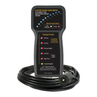
Describes the Electric Brake Force Meter as a professional tool for testing brake controller output and tow-lighting functions.
Explains OEM variations in trailer brake controller design and function, emphasizing that methods evolve.
Provides essential pre-test setup instructions and critical warnings for using the brake force meter.
Step-by-step guide for connecting and preparing the Electric Brake Force Meter for testing.
Alternative method for certain vehicle models (2016-2017) when the standard setup does not establish trailer connection.
Instructions for performing brake force testing, including manual lever and brake pedal application.
Guidance for testing newer vehicles with modules that monitor and control trailer circuits, including initial checks.
Explains the function of the ECU Detected light in identifying vehicle brake controller presence and trailer connection.
Details the meaning of the ECU Detected, Power, and Gain indicator lights and their states.
Provides a table outlining common circuit faults and diagnostic procedures for electric brake systems.
The #9107B Electric Brake Force Meter with Dynamic Load Simulation and Circuit Testing is a professional, high-quality tool designed to test electric brake controller output and all tow-lighting functions without the need for a trailer. This comprehensive device is compatible with most year, make, and model vehicles equipped with 7-spade trailer connections, including newer Ford and GM vehicles. Its primary function is to allow users to view the output of their vehicle's electric brake controller in real-time, providing crucial diagnostic information for both integrated and aftermarket brake controllers.
The core function of the #9107B is to simulate a trailer's electrical load, enabling the vehicle's brake controller to operate as if a trailer were connected. This simulation is dynamic, meaning it can mimic varying load conditions that a real trailer would present. The device features a series of 10 LEDs that illuminate sequentially, indicating the extent of 12V power available at the connector to actuate trailer brakes. This visual feedback allows technicians to assess the brake force output from the vehicle's controller.
Beyond brake force measurement, the #9107B also performs comprehensive circuit testing for all tow-lighting functions. It includes dedicated indicators for:
A key feature is the ECU Detection Light (Yellow), which indicates when the meter detects a discovery pulse signal from the vehicle. Modern vehicles with integrated controllers often limit output to the trailer electric brake circuit until a trailer is detected. The #9107B looks for this pulse and, once detected, illuminates the ECU Detected light and adjusts its built-in trailer simulation load accordingly. This ensures accurate testing even with sophisticated vehicle systems. The Power Light (Red) indicates whether the electric brake circuit has power and continuity.
The #9107B is designed for ease of use, with a clear and intuitive interface. The setup procedure is straightforward:
An alternative setup procedure is provided for 2016 and newer models where brake controllers might search for a trailer signal differently. In such cases, pressing and holding the brake pedal during step 7 of the setup can help establish a "Trailer Connected" message.
During testing, users can:
The device includes important warnings:
The Ground Integrity light will only illuminate when a circuit is completed, and it may flash in sequence with directional circuits, which is normal.
For 2019 and newer vehicles, which often feature modules monitoring and controlling trailer circuits, the tool will energize and default into Trailer Simulation mode once 12V power is on. Users should allow the vehicle's computer to complete its start-up/system status check sequence (indicated by flickering LEDs on the tool) before testing.
While the manual does not detail specific user-level maintenance, it emphasizes the importance of proper setup and handling to ensure the device's longevity and accurate operation. The robust design is intended for professional use, suggesting durability under typical workshop conditions.
The device comes with a Limited One-Year Warranty, covering defects in workmanship or material. This warranty highlights the manufacturer's commitment to quality and provides recourse for users in case of product issues. The warranty specifically excludes wearable parts like batteries (30-day warranty) and battery clips, indicating that these components may require periodic replacement depending on usage.
In case of suspected incompatibility or issues, the manual directs users to contact Innovative Products of America® for support, including potential updates for newer vehicle models. This indicates ongoing support and potential for software or hardware revisions to maintain compatibility with evolving vehicle technologies.
The #9107B is supplied with a soft case (#9107-3) for protection and a 25 ft. 7-Flat Pin Cable (#KCBL-9107-AS), facilitating convenient storage and use. The inclusion of these accessories underscores the device's design for practical, on-the-go diagnostic work.
| Type | Digital Multimeter |
|---|---|
| DC Voltage Ranges | 200mV, 2V, 20V, 200V, 1000V |
| AC Voltage Ranges | 200V, 750V |
| Diode Test | Yes |
| Continuity Test | Yes |
| Power Source | 9V battery |
| Operating Temperature | 0°C to 40°C |
| DC Current Ranges | 200µA, 2mA, 20mA, 200mA, 10A |
| Resistance Ranges | 200Ω, 2kΩ, 20kΩ, 200kΩ, 2MΩ |
| Power Supply | 9V battery |