4
4. While increasing brake pressure, you should see more of the 10 LED
indicators illuminate. Some vehicles or brake controllers may limit output
with brake pedal pressure, unless the vehicle is moving.
5. Release the brake pedal. If any abnormal results were noted, continue to
Circuit Fault Troubleshooting on page 6.
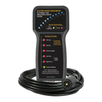
6. Test other lighting and electrical functions such as Left and Right Turn
Signals, Tail/Tag, Brake Lights etc.
WARNING: To avoid overheating, DO NOT hold foot on brake for
intervals longer than 15 seconds.
NOTE: The Ground Integrity light will only illuminate when a circuit is
completed. In other words, if you are only testing left or right directional
circuits, you may notice the Ground Integrity light ashing in sequence with
the directional. This is normal and expected.
NOTICE REGARDING 2019 AND NEWER VEHICLES
Some late model vehicles feature a module which monitors and controls
power to all of the trailer circuits. These modules are typically powered from
the 12V hot lead, which may be labeled as "Trailer Battery" in the fuse box.
When troubleshooting these vehicles, rst check to see if the 12V LED on the
tool is illuminated prior to troubleshooting. If the LED is not illuminated on the
tool, check the vehicle’s fuse and wire connections.
With the 12V power on, the tool will energize and immediately default into
Trailer Simulation mode. Watch the LEDs on the tool and allow the vehicle’s
computer to complete its start-up/system status check sequence prior to
testing. This start-up sequence can be monitored by watching the LED lights
on the tool icker on and off in sequence. The entire start-up sequence
should take less than 30 seconds.
For questions or support, please contact IPA at 845-679-4500, or email
tech247@ipatools.com.